OPERATION MANUAL NIGHTHAWK SERIES MODELS LT-12D, LT-12P DEDICATED LIGHT TOWER (DEUTZ/LOMBARDINI DIESEL ENGINE) (PERKINS DIESEL ENGINE) Revision #1 (08/15/08) To find the latest revision of this publication, visit our website at: www.multiquip.com THIS MANUAL MUST ACCOMPANY THE EQUIPMENT AT ALL TIMES.
PROPOSITION 65 WARNING / REPORTING SAFETY DEFECTS Diesel engine exhaust and some of REPORTING SAFETY DEFECTS If you believe that your vehicle has a defect that could cause a crash or could cause injury or death, you should immediately inform the National Highway Traffic Safety Administration (NHTSA) in addition to notifying Multiquip at 1-800-421-1244.
TABLE OF CONTENTS STOW NIGHTHA WK NIGHTHAWK LT-12 SERIES LIGHT TOWER Proposition 65 ................................................................. 2 Reporting Safety Defects ................................................ 3 Table of Contents ............................................................. 3 Safety Message Alert Symbols ................................... 4-5 Rules For Safe Operation ............................................. 6-7 Operation and Safety Decals ..............................
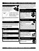
LT-12 SERIES LIGHT TOWER — SAFETY MESSAGE ALERT SYMBOLS FOR YOUR SAFETY AND THE SAFETY OF OTHERS! Safety precautions should be followed at all times when operating this equipment. Failure to read and understand the Safety Messages and Operating Instructions could result in injury to yourself and others. This Owner's Manual has been developed to provide complete instructions for the safe and efficient operation of the LT-12 Series Light Tower.
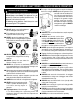
LT-12 SERIES LIGHT TOWER — SAFETY MESSAGE ALERT SYMBOLS CAUTION - Rotating Parts CAUTION - Equipment Damage Messages NEVER operate equipment with covers, or guards removed. Keep fingers, hands, hair and clothing away from all moving parts to prevent injury. Other important messages are provided throughout this manual to help prevent damage to your light tower, other property, or the surrounding environment.
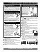
LT-12 SERIES LIGHT TOWER — RULES FOR SAFE OPERATION WARNING - READ THIS MANUAL Failure to follow instructions in this manual may lead to Serious Injury or even Death. This equipment is to be operated by trained and qualified personnel only! This equipment is for industrial use only. The following safety guidelines should always be used when operating the LT-12 Lighttower. ■ The engine of this light tower/generator requires an adequate free flow of cooling air.
LT-12 SERIES LIGHT TOWER — RULES FOR SAFE OPERATION DANGER - High Danger Areas The 5 DANGER items listed below are considered High DANGER areas and should be adhered to. Failing to understand these areas could result in Bodily Harm, Electrical Shock, Electrocution, and even Death! Please pay close attention when operating the light tower. DANGER - Grounding the LT-12 for Operation The LT-12 Light tower is equipped with a ground terminal for your protection.
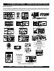
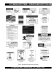
LT-12 SERIES LIGHT TOWER — OPERATION AND SAFETY DECALS Machine Safety Decals This dedicated light tower is equipped with a number of safety decals. These decals are provided for operator safety and maintenance information. The illustration below and on the next page shows these decals as they appear on the machine. Should any of these decals become unreadable, replacements can be obtained from your dealer. Figure 1. Operation and Safety Decals PAGE 8 — LT-12 SERIES LIGHT TOWER — OPERATION MANUAL — REV.
LT-12 SERIES LIGHT TOWER — OPERATION AND SAFETY DECALS Figure 1. Operation and Safety Decals (Continued) LT-12 SERIES LIGHT TOWER — OPERATION MANUAL — REV.
LT-12 SERIES LIGHT TOWER — SPECIFICATIONS (LIGHT TOWER) TABLE 1. SPECIFICATIONS Light Tower Model Engine Model LT-12D LT-12P Deutz F3m1008F/ Lombardini LDW 1003 Diesel Engine Perkins 103-10 Diesel Engine Weight (Dry) 1,550 lbs. (700 kg.) Dimensions See Table 3 Suppor t Points Wind Stability with Genset. Floodlights Lumens Light Coverage Light Termination 5 65 mph (80.
LT-12 SERIES LIGHT TOWER — SPECIFICATIONS (ENGINES) Table 2. Engine Specifications Engine Type Bore X Stroke 2.95 in. X 2.83 in. (75 mm x 72 mm) Displacement 58.21 cu. in. (954 cc) Max Output Standby 10.5 H.P. at 1,800 R.P.M. Fuel Tank Capacity Approx. 30 U.S. Gallons (113 Liters) Standard Idle Speed Fuel Type Lube Oil Capacity 64 Hours 1,800 R.P.M. N0. 2 Diesel Fuel 7.4 U.S. Pints (3.5 Liters) Cooling System Water-cooled Coolant Capacity 8.0 U.S. Pints (3.
LT-12 SERIES LIGHT TOWER — DIMENSIONS Figure 2. Dimensions TABLE 3. DIMENSIONS Reference Letter Description Dimension in. (mm.) A Length (Mast Stowed Position) 170 in. (431 cm.) B Length (Mast Deployed Position) 101 in. (256 cm.) C Max. Height (Mast Deployed Position) 31.5 ft. (9.6 m) D Height (Mast Stowed Position) 74 in. (187 cm.) E Ground Clearance (From Axle) 8 in. (20 cm.) F Width (Tow Ready) 51 in. (129 cm.) G Width (Outriggers Deployed) 109 in. (276 cm.
LT-12 SERIES LIGHT TOWER — GENERAL INFORMATION The Stow LT-12 Series Light Tower is a dedicated general purpose floodlight tower intended for emergency and remote lighting conditions. The light tower can be raised vertically in excess of 31.5 feet (9.6 meters) by means of a manual winch. The tower tensioning system is designed to provide the necessary tension to safely control the pivot of the tower. Outriggers and rear support stand must be deployed prior to raising the mast.
LT-12 SERIES LIGHT TOWER — COMPONENTS Figure 3. Major Components (Control Panel Side) Figure 3 and 4 shows the location of the controls and components for the LT-12 Series Light Tower. The functions of each control is described below: 9. Tower Lock/Release Pin – Pull this pin to release tower mast from cradle support. 1. Mast Rotation Locking Knob – Unscrew this knob to release mast for rotation. 10. Jack Stands – There are two trailer jack stands, which are located at the front and rear of the trailer.
LT-12 SERIES LIGHT TOWER — COMPONENTS Figure 4. Major Components (Front/Rear) 18. Engine Exhaust Pipe – Directs engine exhaust to the rear of the light tower. NEVER block this exhaust pipe with obstructions. ALWAYS place the generator in an area free of obstructions. CAUTION - Burn Hazard The exhaust pipe will become extremely hot when the engine is in use. NEVER touch the exhaust pipe when the engine is running. The possibility exists of severe burns to the skin.
LT-12 SERIES LIGHT TOWER — CONTROL PANEL Figure 5. Control Panel Components and Indicators PAGE 16 — LT-12 SERIES LIGHT TOWER — OPERATION MANUAL — REV.
LT-12 SERIES LIGHT TOWER — CONTROL PANEL Figure 5 shows the location of the basic control panel components for the LT-12 Light Tower. Listed below is a brief explanation of each control or component. 1. Internal Cabinet Light Switch – This switch controls the internal cabinet light for the light tower control panel. When the cabinet door is raised, the light will automatically come on. When the cabinet door closes, the switch is depressed and the light turns off. 2.
LT-12 SERIES LIGHT TOWER — FLOOD LIGHT FOOTCANDLE PLOT Figure 6. Floodlight Footcandle Plot (Area Coverage) PAGE 18 — LT-12 SERIES LIGHT TOWER — OPERATION MANUAL — REV.
LT-12 SERIES LIGHT TOWER — TOWING GUIDELINES Check with your county or state safety towing regulations department before towing your light tower. ■ Inflate tires to correct pressure, inspect tires for cuts, and excessive wear. See Table 3 (Tire Wear Troubleshooting). ■ Check wheel mounting lug nuts with a torque wrench. Torque wheel lug nuts as described in the "Lug Nut Torque Requirements", Table 5.
LT-12 SERIES LIGHT TOWER — TOWING GUIDELINES Figure 7. Safety Chains/ Trailer Coupler Hook-up PAGE 20 — LT-12 SERIES LIGHT TOWER — OPERATION MANUAL — REV.
LT-12 SERIES LIGHT TOWER — TRAILER SAFETY GUIDELINES Tires/Wheels/Lug Nuts Tires and wheels are a very important and critical components of the trailer. When specifying or replacing the trailer wheels it is important the wheels, tires, and axle are properly matched. WARNING - Wheel Repair/Modification DO NOT attempt to repair or modify a wheel. DO NOT install an inter-tube to correct a leak through the rim.
LT-12 SERIES LIGHT TOWER — TRAILER SAFETY GUIDELINES TABLE 4. SUSPENSION TORQUE REQUIREMENTS Item Torque (Ft.-Lbs.) 3/8" U-BOLT MIN-30 MAX-35 7/16" U-BOLT MIN-45 MAX-60 1/2" U-BOLT MIN-45 MAX-50 SHACKLE BOLT SPRING EYE BOLT SNUG FIT ONLY. PARTS MUST ROTATE FREELY. LOCKING NUTS OR COTTER PINS ARE PROVIDED TO RETAIN NUT-BOLT ASSEMBLY. SHOULDER TYPE MIN-30 MAX-50 SHACKLE BOLT Lug Nut Torque Requirements It is extremely important to apply and maintain proper wheel mounting torque on the trailer.
LT-12 SERIES LIGHT TOWER — TRAILER WIRING DIAGRAM Figure 10. Typical Trailer Wiring Diagram LT-12 SERIES LIGHT TOWER — OPERATION MANUAL — REV.
LT-12 SERIES LIGHT TOWER — INSPECTION Before Starting 1. Read all safety instructions at the beginning of manual. 2. Clean the light tower, removing dirt and dust, particularly the engine cooling air inlet and air cleaner. Figure 11. Dipstick 3. Check the air filter for dirt and dust. If air filter is dirty, replace air filter with a new one as required. 4. Check all fastening nuts and bolts for tightness. WARNING - Ventillation Requirements 5.
LT-12 SERIES LIGHT TOWER — INSPECTION Battery Check Fuel Check CAUTION - Diesel Fuel Safety Diesel fuel and its vapors are dangerous to your health and the surrounding environment. Avoid skin contact and/or inhaling fumes. DO NOT smoke while refueling. DO NOT attempt to refuel the light tower if the engine is hot! or running. WARNING - Battery Safety The operator MUST wear the appropriate protective equipment and clothing while handling the battery.
LT-12 SERIES LIGHT TOWER — INSPECTION Coolant (Ethylane Glycol [Green] / Water — 50/50 mix) Use only drinkable tap water. If hard water or water with many impurities is used, the inside of the engine and radiator may become coated with deposits and cooling efficiency will be reduced. An anticorrosion additive added to the water will help prevent deposits and corrosion in the cooling system. See the engine manual for further details.
LT-12 SERIES LIGHT TOWER — INSPECTION WARNING - Respiratory Hazard The engine's exhaust contains harmful emissions. ALWAYS ventilate the exhaust when operating inside tunnels, excavations or buildings. Direct exhaust away from nearby personnel. Before starting the engine perform the following: 1. Be sure to disconnect the electrical load and switch the main circuit breaker and all lamp (4) circuit breakers to the OFF position prior to starting the engine. 6. Bottom tower mast is locked in place. 7.
LT-12 SERIES LIGHT TOWER — STARTUP PROCEDURES Starting the Engine Starting the Engine (Lombardini/Deutz Engines) The Night-Hawk LT-12 Series Light Tower is available with two types of engines (Perkins or Lombardini/Deutz). The engine starting procedure contained within this manual will address both engines.. 1. Open the access panel door on the right-side of the light tower (opposite the fuel tank). Set the door latch in place to hold the door open (up) Starting the Engine (Perkins Engines) 1.
LT-12 SERIES LIGHT TOWER — SHUTDOWN PROCEDURES Normal Shut-down Emergency Shut-down 1. If a load is attached to the generating set of the light tower, remove the load. 1. Turn the ignition key to the OFF position. 2. Set CB-1 thru CB-4 on the control panel to the OFF position. 3. Place the MAIN circuit breaker (Figure 5, Item 4) on the control panel to the OFF position. 4. Wait a few seconds and observe that flood all floodlights are OFF. 5. Let the engine idle for a few minutes with no load. 6.
LT-12 SERIES LIGHT TOWER — MAST OPERATION DANGER - Overhead Obstruction Danger ALWAYS make sure the area above Light tower is open and clear of overhead power lines and other obstructions. The mast extends in excess of 30 ft. (9 meters). Contact with overhead powerlines or other obstructions could result in equipment damage, Serious Injury or Death! DO NOT stand behind the trailer while the mast is being raised or lowered. Serious Injury could result if the mast falls down.
LT-12 SERIES LIGHT TOWER — OPERATION Turning On the Flood Lights Applying an External Load The Main Circuit Breaker (25 amps), and 4 floodlight circuit breakers (10 amps each) are located on the upper control panel (Figure 20). Please note that there is one 10 amp circuit breaker for each floodlight. The Night-Hawk LT-12 Series Light Tower is available with two auxiliary output receptacles (Figure 18).
LT-12 SERIES LIGHT TOWER — MAINTENANCE Use Table 9 shown below as a general checklist to be performed on a daily basis. For more detailed maintenance refer to the Perkins or Lombardini/Deutz engine service manuals. TABLE 9.
LT-12 SERIES LIGHT TOWER — MAINTENANCE Check Cable Wear Servicing the Mast Extension Cable System: The wire rope (cable) that raises and extends the mast is a very important part of the light tower. There is one cable/hand winch system, located on the tounge of the trailer, that raises and extends the light tower mast. There is a second cable/hand winch system located on the mast that serves to raise and lower the two extendable sections of the mast.
LT-12 SERIES LIGHT TOWER — MAINTENANCE General Inspection Prior to each use, the generating set should be cleaned and inspected for deficiencies. Check for loose, missing or damaged nuts, bolts or other fasteners. Also check for fuel or oil leaks. Air Cleaner Every 50 hours: Check dust indicators on control panel. If light is ON, clean the air cleaner element. 1. Un-latch the holding clips and take out the air cleaner element. 2. Clean the inside of the body and cover using a damp cloth. 2 3.
LT-12 SERIES LIGHT TOWER — MAINTENANCE WARNING - Radiator Burn Hazard Allow engine to cool when flushing out radiator. Flushing the radiator while hot! will damage radiator. In addition the possibility of hot! coolant exists which can cause severe burns. Flushing Out Radiator and Changing Coolant 1. Stop the engine and allow to cool. Tighten valve of the corrosion resistor (if equipped). 2. Turn water filer cap slowly and remove it. 3.
LT-12 SERIES LIGHT TOWER — MAINTENANCE Replacing Fuel Filter Light Tower Storage: 1. Set the container under the filter cartridge to catch fuel. For storage of the generator for over 30 days, the following is required: 2. Using a filter wrench, turn the filter cartridge to the left to remove it. 3. Clean the filter holder, fill the new filter cartridge with fuel, coat the packing surface of the filter cartridge with engine oil, then install the cartridge to the filter holder. 4.
LT-12 SERIES LIGHT TOWER — TROUBLESHOOTING (GENERATOR) Practically all breakdowns can be prevented by proper handling and maintenance inspections, but in the event of a breakdown, please take a remedial action following the diagnosis based on the Generator Troubleshooting (Table 10) information shown below and on the following page. If the problem cannot be remedied, please leave the unit just as it is and consult our company's business office or service plant. TABLE 10.
LT-12 SERIES LIGHT TOWER — TROUBLESHOOTING (ENGINE) Practically all breakdowns can be prevented by proper handling and maintenance inspections, but in the event of a breakdown, please take a remedial action following the diagnosis based on the Engine Troubleshooting (Table 11) information shown below and on the following page. If the problem cannot be remedied, please leave the unit just as it is and consult our company's business office or service plant. TABLE 11.
LT-12 SERIES LIGHT TOWER — TROUBLESHOOTING (ENGINE) TABLE 11. ENGINE TROUBLESHOOTING (CONTINUED) SYMPTOM Engine revolution is not smooth. Either white or blue exhaust gas is observed. Either black or dark gray exhaust gas is observed. Deficient output. POSSIBLE PROBLEM SOLUTION Fuel filter clogged or dir ty? Clean or change. Air cleaner clogged? Clean or change. Fuel leak due to loose injection pipe retaining nut? Tighten nut. Injection pump malfunctioning? Repair or replace.
LT-12 SERIES LIGHT TOWER — TROUBLESHOOTING (LAMPS) Practically all breakdowns can be prevented by proper handling and maintenance inspections, but in the event of a breakdown, use Table 12 shown below and the Troubleshooting Guide as a basic guideline for troubleshooting lamp malfunctions. If the problem cannot be remedied, consult our company's business office or service plant. TABLE 12.
LT-12 SERIES LIGHT TOWER — TROUBLESHOOTING (LAMPS) TABLE 12. TROUBLESHOOTING LAMPS (CONTINUED) SYMPTOM POSSIBLE PROBLEM SOLUTION Lamp star ts slowly (ARC does nt strike when switch is first turned on) Defective Lamp? Lamp may glow for extended period of time. Replace after checking voltage and ballast. Circuit breaker trips on lamp star t-up Shor t Circuit or Ground? Check wiring against diagram. Check for shor ts or ground. Normal Lamp Depreciation? Replace Lamp.
LT-12 SERIES LIGHT TOWER — TROUBLESHOOTING (LAMPS) TROUBLESHOOTING GUIDE Use the following procedure and wiring diagram on the opposite page to determine which of the four floodlights is not functioning: Connections: 1. Make sure that floodlight #1 power cable is plugged into the J1 connector on the T-Bar assembly. 2. Make sure that floodlight #2 power cable is plugged into the J2 connector on the T-Bar assembly. 3.
LT-12 SERIES LIGHT TOWER — SCHEMATIC DIAGRAM LIGHT TOWER SCHEMATIC DIAGRAM NOTE Capacitors C1 thru C4 are 480 VAC, 24μf. In addition a 47K Ω (1/2 watt) resistor is installed across the capacitor terminals(may be internal or externally installed). LT-12 SERIES LIGHT TOWER — OPERATION MANUAL — REV.
LT-12 SERIES LIGHT TOWER — DEUTZ ENGINE WIRING PAGE 44 — LT-12 SERIES LIGHT TOWER — OPERATION MANUAL — REV.
LT-12 SERIES LIGHT TOWER — PERKINS ENGINE WIRING LT-12 SERIES LIGHT TOWER — OPERATION MANUAL — REV.
OPERATION MANUAL HERE’S HOW TO GET HELP PLEASE HAVE THE MODEL AND SERIAL NUMBER ON-HAND WHEN CALLING PARTS DEPARTMENT 800-427-1244 FAX: 800-672-7877 310-537-3700 FAX: 310-637-3284 SERVICE DEPARTMENT 800-478-1244 FAX: 310-537-4259 310-537-3700 TECHNICAL ASSISTANCE 800-478-1244 FAX: 310-631-5032 WARRANTY DEPARTMENT 800-421-1244, EXT. 279 FAX: 310-537-1173 310-537-3700, EXT. 279 SALES DEPARTMENT 310-661-4242 FAX: 310-604-9237 877-289-7869 (877-BUY-STOW) © COPYRIGHT 2008, MULTIQUIP INC.