Site Preparation Guide F120 Shared Office 3D Printing System Part No.
Site Preparation Guide Copyright Copyright © 2019-2022 Stratasys Ltd. All rights reserved. No part of this document may be photocopied, reproduced, or translated into any human or computer language in any form, nor stored in a database or retrieval system, without prior permission in writing from Stratasys. This document may be printed for internal use only. All copies, shall contain a full copy of this copyright notice.
Contents Revision Log ................................................................................................. iv Safety............................................................................................................ iv Safe Environment................................................................................................................ iv About the F120 Printer................................................................................... 1 Components ...................
Site Preparation Guide Revision Log Revision Log Revision Date Description of Changes A June 2019 First release of this document. B March 2020 Added 240VAC note. C December 2022 Updated TOC footer. Safety The following basic safety tips are given to ensure safe installation, operation, and maintenance of Stratasys equipment and are not to be considered as comprehensive on matters of safety.
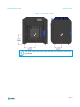
About the F120 Printer Site Preparation Guide About the F120 Printer The Stratasys F120 3D printer incorporates the latest in innovative technology to provide you with precise 3D-printed parts from a CAD design. Stratasys’ Fused Deposition Modeling (FDM) technology provides accurate parts, including internal features, which can be used to field-test form, fit, and function. Direct Digital Manufacturing (DDM) allows for the creation of customized end-use parts straight from 3D CAD data.
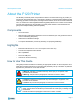
Site Preparation Guide Site Prep Tasks Site Prep Tasks Selecting the Site Decide where to install the printer based on the following: 1. Space Requirements 2. Environmental Requirements 3. Electrical Requirements 4. LAN Requirements The F120 printers are capable of generating vibrations depending mainly on part build geometry and material characteristics. This consideration will need to be taken into account if locating the printer near vibration sensitive equipment.
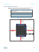
Site Preparation Guide Site Prep Tasks Figure 1: F120 Center of Mass The center of mass dimensions shown are taken from the bottom center of the front left foot.
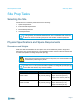
Site Preparation Guide Site Prep Tasks Minimum Operational Clearances Sufficient rear and side clearances allow for proper air circulation, while sufficient front clearance allows enough room for the oven door and drawers to be opened. Right Side Clearance (Includes additional space for material coil boxes) Minimum 20 inches (50.8 cm) Left Side Clearance Minimum 4 inches (10.16 cm) Rear Clearance Minimum 6 inches (15.24 cm) Front Clearance Minimum 20 inches (50.
Site Preparation Guide Site Prep Tasks Environmental Requirements • The F120 printer can be used in any controlled environment. • Air quality conditions with excessive solid particulates (conductive or non-conductive) may result in system damage. • Air quality conditions in which airborne oils are allowed to accumulate on or within the printer can damage the plastic components.
Site Preparation Guide Site Prep Tasks Electrical Requirements AC Power Requirements • 50/60 Hz. • Voltage: 100-132, 200-240 VAC. Caution: In regions with input power above 240 VAC, a step-down transformer must be installed to the system. • Current: 15/7A. • The grounded electrical outlet must connect to either a Euro or a US power cord plug (provided in the Welcome Kit) and must be located within 2 m (80 inches) of the printer.
Site Preparation Guide Receiving the Printer Receiving the Printer Inspect Crate for Damage Before opening the shipping crate, inspect the crate for signs of exterior damage. Report evidence of excessive damage to Stratasys and the shipping company. Preparing For Installation Required Tools and Equipment • Utility knife • A pallet jack or forklift may be required to move the system.
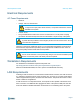
Site Preparation Guide Preparing For Installation Unpacking and Positioning the Printer Make sure that there is at least 70 inches (178 cm) of clearance for the printer before you begin the process of unpacking the printer. 1. Inspect the Tilt Indicators (2) and ShockWatch indicator affixed to the exterior of the cardboard box. If possible, take a picture of these indicators to share with your installation representative.
Site Preparation Guide Preparing For Installation 3. Lift and remove the protective cardboard container panel encasing the printer (Figure 4). Figure 4: Removing the cardboard Shipping Bands Protective Cardboard Container Panel 4. Carefully cut the shipping bands that secure the printer to the pallet (Figure 4). Remove the bands and protective foam pads.
Site Preparation Guide Preparing For Installation 5. Remove all tape and carefully unwrap the printer by pulling the plastic bag downward. Caution: Use care when cutting the plastic bag to avoid scratching the printer’s surfaces. 6. Using a utility knife, cut away and remove the plastic bag’s material ensuring that the bag is not blocking the fork lift opening or the printer’s feet (Figure 5). 7. Remove the protective film from the touchscreen and the logos on the printer’s exterior. 8.
Site Preparation Guide Preparing For Installation 10. Move the printer into its approximate operating location and gently lower it until it rests on its feet. Position the printer to allow at least three feet of clearance on all sides until the installation process is complete, see “Physical Specifications and Space Requirements” (page 2). Refer to Chapter 2 of the F120 User Guide for final setup instructions. 11.
Site Preparation Guide Site Preparation Checklist Site Preparation Checklist Electrical Installation Requirements A dedicated outlet of 100-132, 200-240 VAC~15-7A 50/60 Hz has been installed. The grounded electrical outlet is within 2 meters (80 inches) of the printer. The grounded electrical outlet is able to accept either a Euro or US power cord plug. If utilizing a LAN connection, the LAN connection is within 4 meters (14 feet) of the printer.
www.stratasys.com _____ c-support@stratasys.