INSTALLATION GUIDE INTRODUCTION This guide provides extra information for the Quickscreen Plus System, including Box Contents, Installation Details and FAQs. Please contact Stratco if you have any further questions regarding the installation of your Quickscreen Plus system QUICKSCREEN PLUS BOX CONTENTS (ALL ITEMS SOLD SEPERATELY) This section details the contents of all boxes in the Quickscreen system. Please note that each box is sold seperately.
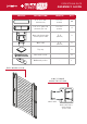
QUICKSCREEN PLUS DESIGN GUIDE QUICKSCREEN PLUS BOX CONTENTS (ALL ITEMS SOLD SEPERATELY) QUICKSCREEN PLUS 2-WAY POST BOX Contains components for 2x 2-Way Posts: COMPONENT QTY DETAILS POSTS 2 2 ½” x 2 ½” x 96” FRICTION FIT INSERT 4 96” POST INSERT 4 24” POST END CAP 2 2 ½” x 2 ½” x 96” SPACER BLOCKS 100 4 packs of 25 QUICKSCREEN PLUS 1-WAY POST BOX Contains components for 2x 1-Way Posts: COMPONENT QTY DETAILS POSTS 2 2 ½” x 2 ½” x 96” FRICTION FIT INSERT 2 96” POST INSERT 2 24”
QUICKSCREEN PLUS BASE PLATE KIT Contains components for 1x Base Plate: COMPONENT QTY DETAILS BASE PLATES 1 4” x 4 ½” SCREWS 4 12 G 3” countersunk screws QUICKSCREEN PLUS INSTALLATION DETAILS INLINE POST INSTALLATION Requires 2-way posts for the middle of the fence run and 1-way posts for each end of the fence run.
QUICKSCREEN PLUS DESIGN GUIDE QUICKSCREEN PLUS DESIGN GUIDE The following design guide is to be used to assist in the design of a fencing layout. Once the layout of a design has been finalised, the exact number and type of boxes can be selected. END/START OF FENCE RUN CREATING A 90° CORNER Use 1-Way Posts to start and end a fence run. Posts are to be fixed to the ground using either Base Plates (for fixing to concrete slabs or other hard surfaces) or by concreting the post in place.
QUICKSCREEN PLUS DESIGN GUIDE: EXAMPLES y wa st Po y wa l ne Pa 1- st Po Pa 2- 1 y wa l ne st Po Pa 2- QTY IN DESIGN st Po y wa 1-WAY POSTS 2 3 st te Ga Po y wa l e an 1- P 1 QTY OF BOXES REQUIRED 2 st Po 1- 11 2 2 y wa l ne y wa 1- st Po l e an P G 1 1 G QTY IN DESIGN y wa st Po 11 QTY OF BOXES REQUIRED 1 1-Way Post Box (2 posts per box) 4 1-WAY POSTS 2 1-Way Post Box (2 posts per box) 2-WAY POSTS 1 2-Way Post Box (2 posts per box) 2 PANEL
QUICKSCREEN PLUS DESIGN GUIDE FREQUENTLY ASKED QUESTIONS Q: Can you cut down the frames and slat? A: Yes, the product is made from aluminum so easy to cut. All you require is a drop saw with an aluminum cutting blade. ›› Quick screen plus is so quick and easy to assemble compared to timber. Once posts installed would work on approx. 5 minutes per section ›› Is generally more cost effective than timber once you take into consideration all factors including maintenance and labor.
FREQUENTLY ASKED QUESTIONS when you push them into the ‘U’ channel. You insert a spacer, provided in the Slat Box, to keep the separation between the slats uniform and there is a ‘post insert’ to fill in any gap at the top or bottom of the ‘U’ channel once all of the slats have been put in place. The top of the post is then capped off with a post cap to provide a nice neat finish.
SIDE FRAME ASSEMBLY GUIDE 1” (25mm) total deduction (cut one end only) Rotate block for 3/8” (9mm) or 13/16” (20mm) spacing STEP 5 STEP 6 Cut aluminium slats 1” (25mm) less than total width of opening. Refer to measurement in step 1. The 1” (25mm) deduction takes into account thickness of side frame on both sides of the screen. Push slats down into side frame ensuring spacer blocks are placed between each slat.
SIDE FRAME ASSEMBLY GUIDE TOOLS REQUIRED FOR INSTALLATION • METAL TAPE MEASURE • SPIRIT LEVEL • PHILLIPS HEAD SCREWDRIVER BIT (FOR DRILL) • CARPENTERS PENCIL • POWER AND/OR CORDLESS DRILL • TIMBER, MASONRY OR STEEL DRILL BITS (AS NEEDED) • DROP SAW WITH SUITABLE BLADE FOR CUTTING ALUMINIUM (IF ADJUSTING HEIGHT OR WIDTH) STEP 1 STEP 2 Take measurement between wall or post at 3 points: top, middle and bottom. Take note of the smallest width measurement.
PEDESTRIAN GATE ASSEMBLY GUIDE PROFILE DESCRIPTION LENGTH QTY 2 1/2” x 5/8” slat 3’ 1 25/32” 20 2 1/2” x 5/8” gate slat 3’ 1 25/32” 4 Gate side frame with slotted spacer infill (1797mm) 5’ 11” 2 5’ 11” 2 Top cap - 2 Hex head screws - 17 D&D latch packer - 1 (65x16mm slat) (65x16mm gate slat) (964mm) (964mm) Outer infill (1797mm) EXPLODED VIEW SIDE FRAME CONSTRUCTION Outer infill Gate side frame with slotted spacer infill
PEDESTRIAN GATE ASSEMBLY GUIDE HEIGHT ADJUSTMENT OF GATE FRAME 1 Using an aluminium saw, cut the gate side frames and outer infills to the required height. Gates are pre-made at 5’ 11” (1797mm) high but can be height adjusted as required.
PEDESTRIAN GATE ASSEMBLY GUIDE 3 ! On a flat protected surface, lay 1x gate side frame with slotted spacer infill and rest against a padded stop and tap slats into place. GATE SLAT POSITIONING · 2x at top of gate · 1x at middle of gate · 1x at bottom of gate NOTE: 4x gate slats must be used even when gate height is reduced 4 Elevate the slats & gate side frame on two padded bearers to allow the second gate side frame to be attached.
PEDESTRIAN GATE ASSEMBLY GUIDE 8 Slide 2x outer infills past end of gate side frame approximately 1/2” (10mm), then using pliers, bend inner legs of outer infill slightly outwards. Tap outer infill back to level with gate side frame. This step is required to stop the outer infill from sliding down. 1/2” (10mm) ! 9 Important note: Using pliers, bend inner legs of outer infill slightly outward to lock into position. Insert top caps into side frames.
SIDE FRAME ASSEMBLY GUIDE TOOLS REQUIRED FOR INSTALLATION • METAL TAPE MEASURE • SPIRIT LEVEL • PHILLIPS HEAD SCREWDRIVER BIT (FOR DRILL) • CARPENTERS PENCIL • POWER AND/OR CORDLESS DRILL • TIMBER, MASONRY OR STEEL DRILL BITS (AS NEEDED) • DROP SAW WITH SUITABLE BLADE FOR CUTTING ALUMINIUM (IF ADJUSTING HEIGHT OR WIDTH) STEP 1 STEP 2 Take measurement between wall or post at 3 points: top, middle and bottom. Take note of the smallest width measurement.
SIDE FRAME ASSEMBLY GUIDE 1” (25mm) total deduction (cut one end only) Rotate block for 3/8” (9mm) or 13/16” (20mm) spacing STEP 5 STEP 6 Cut aluminium slats 1” (25mm) less than total width of opening. Refer to measurement in step 1. The 1” (25mm) deduction takes into account thickness of side frame on both sides of the screen. Push slats down into side frame ensuring spacer blocks are placed between each slat.
1 WAY, 2 WAY & CORNER POST SYSTEM ASSEMBLY GUIDE TOOLS REQUIRED FOR INSTALLATION • • • • METAL TAPE MEASURE SPIRIT LEVEL PHILLIPS HEAD SCREWDRIVER BIT (FOR DRILL) CARPENTERS PENCIL • POWER AND/OR CORDLESS DRILL • TIMBER, MASONRY OR STEEL DRILL BITS (AS NEEDED) • DROP SAW WITH SUITABLE BLADE FOR CUTTING ALUMINIUM (IF ADJUSTING HEIGHT OR WIDTH) 8 FT 1 ⅜ INCHES 8 FT BETWEEN CTRS 8 FT BETWEEN CTRS STEP 1 A) INLINE POST INSTALLATION STEP 1 B) CORNER POST INSTALLATION Set out posts and allow 8 feet* from
1 WAY, 2 WAY & CORNER POST SYSTEM ASSEMBLY GUIDE STEP 4 STEP 5 For 3/8 inch spacing, lay the spacer block flat. For 13/16 inch spacing, stand the spacer block on its end. Push slats down into side frame ensuring spacer blocks are placed between each slat. Install tip: Place spacer block on bottom plate before pushing first slat down so that first slat sits on a spacer block. Spacer blocks supplied in kit allow slat spacing of 3/8 inch or 13/16 inch.