MS2015 OWNER’S MANUAL Mobile Audio System • PLL Synthesizer Stereo Radio • Digital Compact Disc Player • Automatic Memory Storing • Slide Down Detachable Panel • Preset Equalization • Remote Control
CONTENTS Playing all tracks in random ............11 Selecting tracks by AMS/MP3 button.............................11 Display information..........................12 Disc notes ...........................................12 Remote Control Handset..................13 Specification......................................14 Trouble shooting ...............................15 Installation ...........................................3 Take out screw before installation.........3 DIN Front-Mount (Method A) .........
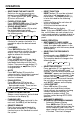
INSTALLATION Notes: TAKE OUT SCREW BEFORE INSTALLATION • Choose the mounting location where the unit will not interfere with the normal driving function of the driver. Before install the unit, please remove the two screws. Take out screws before installation • Before finally installing the unit, connect the wiring temporarily and make sure it is all connected up properly and the unit and the system work properly. • Use only the parts included with the unit to ensure proper installation.
INSTALLATION Sleeve Note: to install the short threading terminal of the mounting bolt to the back of the unit and the other long threading terminal to the dashboard. Spring Washer L Key Hex Nut Metal Strap Mounting Bolt R Key Plain Washer Tapping Screw 4. Mount the sleeve by inserting the sleeve into the opening of the dashboard and bend open the tabs located around the sleeve with a screwdriver. Not all tabs will be able to make contact, so examine which ones will be most effective.
INSTALLATION 4. After removing the outer trim ring, press OPEN/CLOSE button again to slide the front panel up. Then insert both of the supplied keys into the slots at the left and right sides of the unit, then pull the unit out of the dashboard. DIN REAR-MOUNT (Method B) If your vehicle is a Nissan or a Toyota, follow these mounting instructions.
USING THE DETACHABLE FRONT PANEL To Detach the Front Panel 1. Press the OPEN/CLOSE button, the front panel will slide down. Bottom Button 2. When the panel bracket is in slide up position, insert a side of the front panel to its proper position and push the other side into the panel bracket, a ‘click’ sound should be heard. Open 2. Press the OPEN/CLOSE button again, the front panel will slide up. Front Panel Open 3.
WIRING CONNECTION MAIN UNIT ANTENNA CONNECTOR RED IGNITION SWITCH (ACC+) MEMORY BACK-UP (B+) GROUND (B–) POWER ANTENNA FRONT Lch SPEAKER REAR Lch SPEAKER YELLOW (BROWN) Rch RED FRONT RCA LINE OUTCABLE CHOKE BOX Lch WHITE BLACK (GREY) REAR RCA LINE OUT CABLE Rch RED Lch WHITE BLUE WHITE GREY WHITE/BLACK GREY/BLACK GREEN VIOLET GREEN/BLACK VIOLET/BLACK 7 FRONT Lch SPEAKER REAR Rch SPEAKER
OPERATION LOCATION OF KEYS 7 10 8 15 11 13 19 9 8 12 3 2 1 20 21 22 14 4 1. 2. 3. 4. 5. 6. 7. 8. 9. 10. 11. 12. 23 6 18 16 17 5 13. 14. 15. 16. 17. 18. MON Button LOC Button MUT Button LED Disc slot MOD Button OPEN/CLOSE Button ( ) Liquid Crystal Display POWER ( ) PUSH SEL Remote Sensor (IR) Reset Button 19. 20. 21. 22. 23.
OPERATION • RESET FUNCTION RESET button (12) must be activated with either a ball point pen or thin metal object. The RESET button (12) is to be activated for the following reasons: - Initial installation of the unit when all wiring is completed. - All the function buttons do not operate. - Error symbol on the display. Note: If you press RESET button (12) and the unit still does not work, please use a cotton swab soaked in isopropyl alcohol to clean the socket on the back of the front panel.
OPERATION • PAUSING PLAYING Press PAU button (20) to pause CD player. Press it again to resume play. stations are stored into the corresponding preset number button positions. - Program Scanning Press AMS button (18) shortly to scan preset stations. When the signal strength level of a station is more than the threshold level of the stop setting, the radio will hold at that preset number for several seconds, then releases and searches again.
OPERATION • PREVIEWING ALL TRACKS Press SCN button (21) to play first several seconds of each track on the current disc. Press again to stop intro and listen to track. buttons to list all songs under this directory and select the title. - Press BND/LOU (ENT) button to confirm title, and start play. - Repeat the above steps if the newly selected title is again a directory. Searching From Root Directory Press AMS (MP3) button three times.
OPERATION KEY Assigned IN Searching mode (Table 1) AMS Mode Select BND/LOU ENTER M1 A, B, C, 1 M2 D, E, F, 2 M3 G, H, I, 3 M4 J, K, L, 4 M5 M, N, O, 5/ Directory DOWN M6 P, Q, R, 6/ Directory UP MOD S, T, U, 7 MANU/SKIP DOWN V, W, X, 8 MANU/SKIP UP Y, Z, SPACE, 9 DISC NOTE A. Notes on discs: 1. Attempting to use non-standard shape discs (e.g. square, start, heart) may damage the unit. Be sure to use round shape CD discs only for this unit. 2. Do not stick paper or tape etc.
REMOTE CONTROL HANDSET 1 7 4 3 8 9 6 5 13 2 12 10 11 14 15 FUNCTION KEYS & CONTROL 1. 2. 3. 4. 5. 6. 7. 8. 9. 10. PWR DSP (0) SEL VOL VOL BND (ENTER) MOD (7) TUNE/SEEK TUNE/SEEK AMS (MP3) = = = = = = = = = = 11. 12. 13. 14. 15.
SPECIFICATION GENERAL Power Supply Requirements Chassis Dimensions Tone Controls - Bass (at 100 Hz) - Treble (at 10 KHz) Maximum Output Power Current Drain : DC 12 Volts, Negative Ground : 178 (W) x 165 (D) x 50 (H) : : : : ± 10 dB ± 10 dB 4 x 55 Watts 15 Ampere (max.) CD PLAYER Signal to Noise Ratio Channel Separation Frequency Response : More than 55 dB : More than 45 dB : 40 Hz - 18 KHz RADIO FM 87.5 to 107.9 MHz 10.
TROUBLE SHOOTING Before going through the check list, check wiring connection. If any of the problems persist after check list has been made, consult your nearest service dealer. Symptom No power. Disc cannot be loaded or ejected. Cause Solution The car ignition switch is not on. If the power supply is connected to the car accessory circuits, but the engine is not moving, switch the ignition key to “ACC”. The fuse is blown. Replace the fuse. Presence of CD disc inside the player.
Error Code showing on display Cause ERROR 1 Mechanism problem ERROR 2 Playback errors: Remedy Press “RESET” button. Dirty disc Clean the disc and load it as instruction manual mentioned. Disc is loaded up side down Load disc with label facing up. Disc is scratched Try another disc. Disc carries data which cannot be supported by the unit Try another disc.
MS2015 GUIDE D’UTILISATION Système de radio mobile • Radio stéréo à boucle de verrouillage de phase ‘PLL’ • Lecteur de disques compacts numériques • Programmation automatique des stations en mémoire • Face amovible escamotable • Égaliseur préréglé • Télécommande
TABLE DES MATIÈRES Effectuer une pause de la lecture ....11 Entendre le début de chaque piste .11 Répéter la même piste ....................11 Jouer toutes les pistes dans le désordre ..........................................11 Choisir les pistes à l’aide de la touche AMS/MP3 ........................................11 Renseignements relatifs à l’affichage ......12 Remarques sur les disques.................12 Télécommande..................................13 Spécifications....................................
INSTALLATION Remarques : • Sélectionnez l’emplacement de montage de façon à ce que l’appareil ne nuise pas aux manoeuvres du conducteur. • Avant de finaliser l’installation de l’appareil, branchez temporairement les fils afin de vérifier si tout est raccordé correctement et si le système fonctionne bien. • Afin d’assurer que l’installation de l’appareil est adéquate, utilisez uniquement les pièces incluses. L’utilisation non autorisée de pièces pourrait occasionner un mauvais fonctionnement ou un bris.
INSTALLATION Manchon Clé de gauche Remarque : pour installer la borne filetée courte du boulon de montage à l’arrière de l’appareil et l’autre borne filetée longue au tableau de bord. Rondelle à ressort Écrou hexagonal Sangle de métal Boulon de montage Clé de droite Rondelle ordinaire Vis de taraudage 4. Montez le manchon en l’insérant dans l’ouverture du tableau de bord et en repliant les languettes situées autour du manchon à l’aide du tournevis.
INSTALLATION 4. Après avoir retiré la garniture extérieure, appuyez de nouveau sur la touche OPEN/CLOSE pour glisser le panneau avant vers le haut. Ensuite, insérez les deux clés incluses dans les fentes de gauche et de droite et sortez l’appareil du tableau de bord. INSTALLATION DIN PAR L’ARRIÈRE (MÉTHODE B) Si votre véhicule est un Nissan ou un Toyota, suivez ces instructions de montage.
UTILISER LA FACE AMOVIBLE Dégager la face amovible 1. Appuyez sur la touche d’ouverture et de fermeture OPEN/CLOSE et la face amovible glissera vers le bas. Bouton inférieur 2. Lorsque le support de la face est glissé vers le haut, insérez l’un des côtés de la face dans sa position appropriée et appuyez le côté opposé dans le support de la face, vous entendrez un déclic lorsqu’elle sera en place. Ouvrir 2. Appuyez de nouveau sur la touche OPEN/CLOSE pour que la face amovible glisse vers le haut.
CONNEXION DES CÂBLES UNITÉ PRINCIPALE CONNECTEUR D’ANTENNE Commutateur d’allumage (ACC+) Sauvegarde de la mémoire (B+) ROUGE JAUNE MISE À LA MASSE (B-) NOIR Antenne électrique BLEU Haut-parleur avant de gauche Haut-parleur arrière de gauche (BRUN) CÂBLE DE SORTIE DE LIGNE RCA AVANT CIRCUIT DE DÉPART Canal droit ROUGE Canal gauche BLANC (GRIS) CÂBLE DE SORTIE DE LIGNE RCA ARRIÈRE Canal droit ROUGE Canal gauche BLANC BLANC GRIS BLANC/NOIR GRIS/NOIR VERT VIOLET VERT/NOIR VIOLET/NOIR 7
FONCTIONNEMENT EMPLACEMENT DES COMMANDES 7 10 8 15 11 13 19 9 8 12 3 2 1 20 21 22 14 4 1. 2. 3. 4. 5. 6. 7. 8. 9. 10. 11. 12. 13.
FONCTIONNEMENT La touche de réinitialisation ‘RESET’ (12) doit être activée à l’aide de la pointe d’un stylo ou d’un petit objet métallique. Cette touche peut être utilisée dans les cas suivants : - Lors de l’installation initiale, lorsque tous les raccords sont complétés. - Lorsque les touches de fonctionnement ne peuvent pas être activées. - Lorsque le symbole d’erreur appar aît à l’affichage.
OPERATION cycle. Les six stations dont la réception est la plus forte seront entrées en mémoire. Vous pourrez y accéder en appuyant sur la touche du préréglage correspondant. - Balayage des stations programmées Appuyez brièvement sur la touche ‘AMS’ (18) pour balayer les stations préréglées. Lorsque la force du signal de la station est supérieure au niveau du seuil en mode d’arrêt, l’appareil fait une pause à chaque station pendant quelques secondes, relâche la station, puis poursuit la recherche.
OPERATION • CHOISIR LES PISTES EN UNE SEULE ÉTAPE Pendant la lecture d’un CD, appuyez sur la touche (16) ou sur (17) pour vous déplacer vers la piste précédente ou suivante. Le numéro de la piste sera affiché à l’écran. • EFFECTUER UNE PAUSE DE LA LECTURE Appuyez sur la touche ‘PAU’ (20) pour effectuer une pause du CD MP3. Appuyez de nouveau sur cette touche pour reprendre la lecture.
OPERATION • RENSEIGNEMENTS RELATIFS À L’AFFICHAGE Appuyez sur la touche ‘DSP’. Si les données de l’étiquette ID3 TAG sont offertes, elles seront affichées en appuyant sur cette touche. L’étiquette TAG supportée est le nom de la chanson, l’artiste, l’album, l’année et les commentaires. Si elles ne sont pas offertes, les indications de “nom de chanson inconnu, artiste inconnu, aucun titre d’album, année inconnue et aucuns commentaires” apparaîtront à l’écran ACL.
TÉLÉCOMMANDE 1 7 4 3 8 9 6 5 13 2 12 10 11 14 15 TOUCHES DES FONCTIONS ET LES COMMANDES CORRESPONDANTES 1. PWR 2. DSP (0) 3. SEL 4. VOL 5. VOL 6. BND 7. MOD (7) 8. SYNTONISATION/RECHERCHE 9. SYNTONISATION/RECHERCHE 10. AMS (MP3) 11. M1 – M6 12. PAU 13. SCN 14. RPT 15.
SPÉCIFICATIONS GÉNÉRALES Alimentation Dimensions du châssis Commandes de tonalité - Graves (à 100 Hz) - Aigus (à 10 KHz) Puissance de sortie maximum Drain de courant : 12 volts CC, masse négative : 178 (L) ¥ 160 (P) ¥ 50 (H) : : : : +/-10 dB +/-10 dB 4 x 55 watts 15 ampères (max.
GUIDE DE DÉPANNAGE Avant de vérifier les points ci-dessous, vérifiez les raccords de vos fils. Si, après vérification de tous les points ci-dessous, le problème persiste encore, consultez le marchand qui vous a vendu l’appareil ou un centre de service autorisé. Cause Solution La clé de contact n’est pas tournée. Si le bloc d’alimentation est bien raccordé à la borne accessoire de la clé de contact, tournez la clé en position accessoire ‘ACC’. Le fusible est sauté. Remplacez le fusible.
Codes d’erreur apparaissant à l’affichage ERREUR 1 ERREUR 2 Cause Solution Problème du mécanisme Appuyez sur la touche de réinitialisation ‘RESET’. Erreurs de lecture; Le disque est sale. Nettoyez le disque et chargez-le selon les instructions du guide d’utilisation. Le disque est chargé à l’envers. Chargez le disque en vous assurant que l’étiquette soit orientée vers le haut. Le disque est égratigné. Essayez un autre disque.