08-09-01-009-0 OWNER’S MANUAL
TABLE OF CONTENTS Notices ……………………………………………………………………………..….……………... Page 1 FCC Notice System Scope of Use and Warnings System Installation and Usage Reacting To Alerts Use of Chemicals 1. Technical Specifications ……………………………………………………………………………. Sensor/Transmitter Module Display/Receiver Module Page 2 2. Components Part List ……..………………………………………………………………………... Page 3 3. Getting Started ………………………………………………………………………………………. How it works Handling Alerts Page 4 4. Sensor/Transmitter Module …………………………...
NOTICE FCC Notice This device complies with Part 15 of the FCC Rules. Operation is subject to the following two conditions: (1) this device may not cause harmful interference, and (2) this device must accept any interference received, including interference that may cause undesired operation. This equipment has been tested and found to comply with the limits for a Class B digital device, pursuant to Part 15 of the FCC Rules.
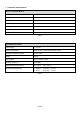
1. TECHNICAL SPECIFICATION Sensor / Transmitter Module Operating Temperature Range -40°C to +125°C Operating Humidity 100% Weight 32 gram Size (LxWxH) 71 mm x 36 mm x 21 mm Battery Life (Projected) 5 years in normal use Transmitting Frequency 433.92 MHz Transmitter Activation By pressure change Table 1 Display/Receiver Module Power Supply 9 ~ 15 V DC Current Consumption 18mA nominal, 130mA during alert @ 12V DC.
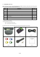
2. COMPONENTS PART LIST After unpacking, ensure that all the parts listed below are available. Should any part(s) is/are found missing, please return to your dealer and get a complete replacement set.
3. GETTING STARTED How it works Pressure and temperature information are sent to the Receiver and displayed on the LCD display. When an underinflated, over-inflated or over-heated tire is detected, the Receiver will emit an audible warning and activate the backlight to warn the driver. The alerts depend on threshold value set for pressure and temperature. Either the factory or manual preset value can be selected. Handling Alerts When any of the tires is not within the threshold limits (e.g.
4. SENSOR/TRANSMITTER MODULE Installation Caution: Qualified personnel must perform the following installation procedures to ensure that the Sensor/Transmitter Module are properly installed and undamaged. It does not include any standard procedures normally required in the process of replacing a tire but due care should be taken to ensure that the sensors are not damaged.
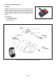
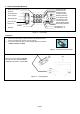
Installing Sensor/Transmitter Module The following is suggested installation sequence: Transmitter Red (1) Yellow (2) Blue (3) Green (4) White (5) Wheel Position Left Front Right Front Right Rear Left Rear *Spare Tire Figure 3a Figure 3b Figure 4 Figure 5 Figure 6 Figure 7a Table 5 • • • • • • • Remove the original tire valve from tire rim. Insert the provided tire valve into rim valve hole. (Figure 3a & Figure 3b.) Position the Sensor/Transmitter rear to the mounted tire valve.
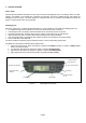
5. DISPLAY/RECEIVER MODULE Pressure in Kpa Pressure in Psi Pressure in Bar. ID learning mode. Backlight selection. Measured Pressure Readout Front Right Tire Front Left Tire ID exchange mode. Tire monitor mode. Pressure alert icon. Sensor Battery Status User setting selected. Rear Right Tire Rear Left Tire Spare Tire Measured Temperature Readout Temperature in °C. Temperature in °F Figure 8 LCD Display Installation 1.
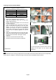
Recommended Installation for Display/Receiver Module and Bracket Figure 11 1. Determine the desired location for Display/Receiver Module. Refer Figure. 12 for possible locations 2. Peel off the film covering the piece of black adhesive double-sided-tape film on the back of the display bracket. (Figure 13) Figure 13 3. Mount the Display Module to the desired location. (Figure 14) Figure 14 4. Apply pressure around the Display/Receiver Module for maximum mounting of the module to the car windscreen.
6. PROGRAMMING Figure 20 To Enter Programming mode Main Menu 1. Ensure that the power is switched ON 2. Press and hold [M] button for 3 sec or more In programming mode toggle the [+] or [-] button for desired programming mode from S-1 to S-6. To accept the desired programming mode press [OK] button. To Quit Programming Main menu Display mode, press and hold [M] button for 3sec or more.
Display Mode (S- 1) Press [OK] to enter programming display mode. ‘ror’ or ‘noL’ will blink to indicate that it is ready to accept changes. Toggle [+] or [-] button to alternate between Rotation Mode and Normal Mode. Rotation Mode Each of the tires will be ‘scanned’ for the reading. The rotation will begin from Front Left tire, followed by Front Right Tire, Rear Right Tire, Rear Left Tire and the cycle will begin again with the Front Left Tire. This is indicated by a blinking tire icon.
Programming Threshold Setting (S- 2) Press [OK] to enter the Threshold setting mode. There are two available threshold setting mode available, 1. User setting (USr) 2. Factory Default (FAC) Figure 25 Upon entering this mode, the selected threshold setting mode will blink, indicating that the currently selected mode and it is ready to accept changes of the mode. Pressing the [ + ] button or [ - ] button to toggle the mode to USr or FAC.
Sensor ID Exchange Mode (S- 3) After rotation of tires, the Sensor ID data in the receiver must be changed accordingly to ensure that it indicates the correct tire when there are any irregularities. Step 1 Press [OK] button to enter ID Exchange mode. Figure 31 Step 2 The Front left tire icon and its corresponding ID digit will blink. 1. Use [+] and [-] button to change the selected Sensor ID digit. 2. Press [OK] to confirm the changes and the next ID digit will blink accordingly. 3.
Sensor ID Learning Mode (S- 4) For programming of a new receiver unit with ID Learning Mode, refer to the following steps. Step 1 Press [OK] button to enter the ID learning Mode. Figure 35 Step 2 1. The front left tire icon will blink. Toggle [+] or [-] button to select the desired tire and press [OK] to accept the desired location. The corresponding tire ID number blinks (once per second) to indicate that it is ready to accept new Sensor ID input. 2.
Turn Backlight On/Off (S- 5) For programming backlight setting, refer to the following steps. 1. Backlight On (Permanent On) 2. Backlight Off (Auto) Step 1 Press [OK] button to enter Backlight programming mode. Figure 38 Step 2 The default-selected option will blink. 1. To change the selection On-Off press [+] or [-] button. 2. To confirm the selection press [OK] button. 3.
7. Troubleshooting Guide Symptoms Possible cause(s) Solution No display on LCD panel. No power. Check connections of Power cable at both ends. Ensure that the connection is on the correct polarity and properly grounded. No display on LCD panel. Faulty Unit. Contact your dealer for a replacement. The unit does not activate when the POWER key button is pressed. The car ignition has not been turned ON. Turn the ignition key to ACC position.
9.
This Page is Intentionally Left Blank Page 17
This Page is Intentionally Left Blank Page 18
This Page is Intentionally Left Blank Page 19