
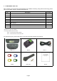
User's Manual
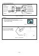

Installing Sensor/Transmitter Module
Note
The following is suggested installation sequence:
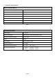
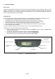
Transmitter Wheel Position
Red (1) Left Front
Yellow (2) Right Front
Blue (3) Right Rear
Green (4) Left Rear
White (5) *Spare Tire
Table 5
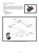
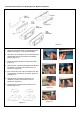
• Remove the original tire valve from tire rim.
• Insert the provided tire valve into rim valve hole.
(Figure 3a & Figure 3b.)
• Position the Sensor/Transmitter rear to the mounted
tire valve. (Figure 4),
• Insert the provided screw to the Sensor as shown in
figure 5 and screw the Sensor to the tire valve.
(Figure 6). The tire valve will be the reference
position of the sensor in order not to damage the
sensor when removing tire from the wheel. Ensure
that the screw is properly tightened to hold the
sensor.
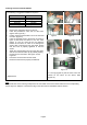
• Attach the corresponding color tag to the valve stem
and secure it with the valve cap by carefully twisting
the tag onto the valve stem. See Figure 7a and
Figure 7b.
• Proceed to mount the tire onto the wheel.
• Ensure that the tires are properly re-balanced.
*Optional Part
Figure 3a Figure 3b
Figure 4 Figure 5
Figure 6 Figure 7a
Figure 7b
# = The tag (Figure.7a) has the same color and
number as the same as the sensor label
(Figure.7b).
#
Ensure that each of the color tag correspond to the color label on the sensor. Refer Table 5 for the corresponding
sensor tag to tire. Keep the colored sensor tag on the valve stem for installation and tire rotation.
Page 6