
User's Manual
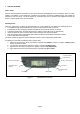
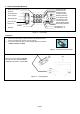

5. DISPLAY/RECEIVER MODULE
Sensor Battery Status
User setting selected.
ID learning mode.
Backlight selection.
Temperature in °C.
Temperature in °F
ID exchange mode.
Tire monitor mode.
Pressure alert icon.
Pressure in Kpa
Pressure in Psi
Pressure in Bar.
Measured Temperature
Readout
Rear Right Tire
Front Right Tire
Measured Pressure
Readout
Front Left Tire
Rear Left Tire
Spare Tire
Figure 8 LCD Display
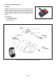
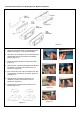
Installation
1. Insert the Power Supply Cable connector into Receiver socket,
which is located at the top rear. (Figure 9 &10).
2. Connect the other end of the Power Supply Cable to the vehicle
+12VDC, Ground and ACC.
Figure 9 Connection of Power Cable
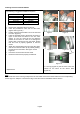
RED color wire to vehicle +12V DC,
BLACK color wire vehicle Ground,
ORANGE color Wire to vehicle ACC,
Figure 10 Wiring Diagram
Page 7