
User manual


PART 1 • English
5
English
2.0 YOUR RECEIVER
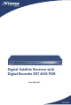
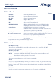
2.1 Front Panel
Figure 1
1. STANDBY Power On/Standby button
2. VOL-/VOL+ Increase/decrease volume level
3. CH -/CH+ Channel Up/Down buttons
4. MENU Displays Main menu
5. OK Confirm selection
6. REC Start record of current channel
7. MODE INDICATOR RED light indicates that the receiver is in STAND-BY mode.
GREEN light indicates that the receiver is in AWAKE mode.
8. 4 digits display In STAND-BY mode current time is indicated.
In AWAKE mode is current channel number or current time
(as selected in system set-up) indicated.
9. VFD display In AWAKE mode is the current channel name displayed.
10. Common interface slots* Insert your common interface modules to this slot in order to
have access to appropriate encrypted channels.
11. USB connector* Use this connector to connect USB media storage device to
your receiver.
* Compatible to the most popular USB-Storage devices
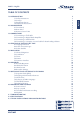
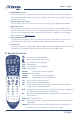
2.2 Rear Panel
Figure 2
1. SAT IN (Tuner 1 & 2)
To connect the coaxial cable from your LNB on the satellite dish or one of the SAT OUT
connectors to this connector.
2. SAT OUT (Tuner 1 & 2)
To connect SAT IN from other Tuner with loop cable.
NOTE: connection of SAT IN and SAT OUT depends from antenna installation and
described in details in part 3.3 of this manual.
3. ANT IN
To connect your aerial antenna or cable TV using coaxial cable.
4. TO TV
If you do not use a SCART cable to connect your receiver to your TV, or if you have connected
a cable to the ANT input, you will have to use this connector to connect the receiver to your TV
by using a coaxial cable. You have to setup channel and system of modulation as described in
part 5.2.5
5. TV SCART Connector
Use this connector to connect your receiver with your TV set using a SCART cable.