22 TON AIR/HYDRAULIC SERVICE JACK OWNER’S MANUAL WARNING: Read carefully and understand all ASSEMBLY AND OPERATION INSTRUCTIONS before operating. Failure to follow the safety rules and other basic safety precautions may result in serious personal injury.
Thank you very much for choosing a Strongway product! For future reference, please complete the owner’s record below: Model: _______________ Purchase Date: _______________ Save the receipt, warranty and these instructions. It is important that you read the entire manual to become familiar with this product before you begin using it. This machine is designed for certain applications only. The distributor cannot be responsible for issues arising from modification.
SAVE THESE INSTRUCTIONS IMPORTANT SAFETY CONSIDERATIONS JACK USE AND CARE Do not modify the Jack in any way. Unauthorized modification may impair the function and/or safety and could affect the life of the equipment. There are specific applications for which the Jack was designed. Always check of damaged or worn out parts before using the Jack. Broken parts will affect the Jack operation. Replace or repair damaged or worn parts immediately. Store idle Jack.
Safety Always follow safety precautions when installing and operating this jack. Keep all decals on the unit clean and visible. Before proceeding ensure that you fully understand and comprehend the full contents of this manual. Failure to operate this equipment as directed may cause injury or death. The distributor is not responsible for any damages or injury caused by improper use or neglect. WARNING: Always use Jack Stands! DO NOT USE wood blocks or any other non-approved load sustaining devices.
* Position the Jack Position the jack to only lift on the areas of the vehicle as specified by the vehicle manufacturer. * Always Use Jack Stands After lifting the vehicle always support the load with appropriately rated vehicle Jacks stands before working on the vehicle. * Do Not Overload Jack Do not overload this jack beyond its rated capacity. Overloading this jack beyond its rated capacity can cause damage to or failure of the jack.
Spectators -Do not allow bystanders around the jack or under the load supported only by the jack. -Do not allow anyone in the vehicle while the jack is in use. Keep all bystanders away from vehicle when in use. Inspection -Inspect the jack carefully before each use. Ensure the jack is not damaged, excessively worn, or missing parts. -Do not use the jack unless it is properly lubricated. -Using a jack that is not in good clean working condition or properly lubricated may cause serious injury.
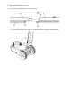
ASSEMBLY All numbers in parenthesis () refer to the index number from the parts breakdown. 1. Familiarize yourself with the jack. 2. Refer to picture when performing this step. Take off the screw located on handle piece 1; Attach handle pieces 1 and 2 making sure to align the holes on both sections. Reinsert the screw and tighten. Check to that handle is in perfect alignment with internal lowering valve mechanism. (Handle lowering mechanism must be in perfect alignment or release mechanism will not work.).
3. Attach handle position release rod. 4. Check movement of both Pieces before next step. 5. Insert the handle (37) into handle sleeve (45) and affix the handle (37) using bolt (46).
6. Carefully place the adapter plate (40) onto the handle (37) with U-bolts (44), washer (43), lock washer (42) and nut (41). Place extension adapters on the plate and secure with spring clips (39). WARNING: Do not lift or carry jack by handle. Handle could dislodge and jack may fall, resulting in possible injury or property damage.
3. Close the release valve by turning the handle knob clockwise until firm resistance is felt. 4. When the saddle reaches Max. Lift Height, turn the handle knob counter-clockwise.
5. When the saddle reaches Min. Lift Height, with a flat blade screwdriver, push the oil fill plug slightly to the side to purge trapped air from system. 6. Close the release valve by turning the handle knob clockwise until firm resistance is felt. 7. Jack is now ready for use. Check for proper pump action. BEFORE USE 1. Before using this product, read the owner's manual completely and familiarize yourself thoroughly with the product and the hazards associated with its improper use. 2.
3. Pour a teaspoon of good quality, air tool lubricant into the air supply inlet of the lift control valve. (See illustration) Connect to air supply and operate for 3 seconds to evenly distribute lubricant. 4. Check and that the pump operates smoothly before putting into service. 5. This product is fitting use standard 1/4" NPT air fitting. If changing the fitting is required, install a 1/4" NPT fitting of your choice, ensure that thread tape or compound is used to seal connection. 6.
6. Close the release valve by turning it clockwise until it is firmly closed. 7. Connect air source to the air supply inlet (26). 8. Close the release valve by turning the handle knob clockwise until firm resistance is felt.
9. Before raising the vehicle double check and verify the saddle is centered and also has full contact with the lifting point. 10. Squeeze air trigger to lift until saddle contacts load. (To stop air operation, simply release the grip on the lift control valve.) Continue to pump the jack to lift the vehicle to the desired height. 11. After lifting, support the load with appropriately rated vehicle support stands before working on the vehicle.
4. Carefully open the Release Valve by slowly turning the handle counterclockwise. (Do not allow bystanders around the jack or under the load when lowering the jack. 5. After removing jack from under the vehicle,fully retract the jack to reduce ram exposure to rust and contamination. 6. After removing jack from under the load, push ram and handle sleeve down to reduce exposure to rust and contamination. WARNING: USE EXTREME CAUTION WHEN LOWERING THE JACK. THE JACK HANDLE MAY TURN RAPIDLY.
MAINTENANCE INSTRUCTION If you use and maintain your equipment properly, it will give you many years of service. Follow the maintenance instructions carefully to keep your equipment in good working condition. Never perform any maintenance on the equipment while it is under a load. Inspection You should inspect the product for damage, wear, broken or missing parts (e.g.: pins) and that all components function before each use. Follow lubrication and storage instructions for optimum product performance.
TO ADD OIL: 1. Position the jack on level ground and lower the saddle. 2. Remove the oil plug.
3. Fill the oil case until oil level is just beneath the lower rim of the oil fill hole. 4. Replace oil plug. 5. Perform the Air Purge Procedure. KEEP DIRT AND OTHER MATERIAL CLEAR WHEN POURING.
TO REPLACE OIL: 1. Position the jack on level ground and lower the saddle. 2. Open release valve by turning handle counterclockwise.
3. Remove the oil fill plug. 4. Remove the handle. 5. Turn the jack on its side so that old oil will drain from the oil fill hole.
6. Fill the oil case until oil level is just beneath the lower rim of the oil fill hole. 7. Replace oil plug. 8. Perform the Air Purge Procedure. ADDITIONAL WARNINGS: DO NOT USE MOTOR OIL IN THE JACK. ONLY USE ANTI-FOAMING JACK OIL. ALWAYS USE A GOOD GRADE HYDRAULIC JACK OIL. DO NOT USE HYDRAULIC BRAKE FLUID, ALCOHOL, GLYCERINE, DETERGENT, MOTOR OIL OR DIRTY OIL. USE OF A NON-RECOMMENDED FLUID CANCAUSE DAMAGE TO A JACK.
LUBRICATION Periodically check the pump piston and ram for signs of rust or corrosion. Clean as needed and wipe with an oil cloth. NEVER USE SANDPAPER OR ABRASIVE MATERIAL ON THESE SURFACES! Storage When not in use, store the jack with pump piston, hydraulic ram and saddle fully retracted.
HANDLE ASSEMBLY DIAGRAM 23
HANDLE ASSEMBLY PARTS LIST Index # 1 2 3 4 5 6 7 8 9 10 11 12 13 14 15 16 17 18 19 20 21 22 Part No. TQ22001.3.2-01 TQ22001.3.2-04 T32002c-2 GB879 TQ22001.3-07 TQ22001.3-06 TQ22001.3-05 TQ22001.3-04 GB6170 TQ22001.3-03 TQ22001.3-02 TQ22001.3-01 TQ22001.3.1-04 GB879 GB70 TQ22001.3.2-05 TQ22001.3.1-06 TQ22001.3.1-01 GB879 TQ22001.3.1-05 GB97.
ASSEMBLY DIAGRAM 25
ASSEMBLY PARTS LIST Index # 23 24 25 26 27 28 29 30 31 32 33 34 35 36 37 38 39 40 41 42 43 44 45 46 47 48 49 50 51 52 53 54 Part No. TQ22001-06 TQ22001.1 TY20002.1.2 TQ22001.8 TQ22001-07a TQ22001.9a GB818 GB97.1 GB5781 GB93 GB97.1 GB818 GB896 TQ22001.5 TQ22001.3 TQ22001.1-01 TQ22001-03 TQ22001-02 GB6170 GB93 GB97.1 TQ22001-01 TQ22001-05 TQ22001-04 TQ22001.4b GB97.1 GB93 GB5781 TQ22001.6 TQ22001.4b TQ22001.10 TQ22001.1.
POWER UNIT ASSEMBLY 27
POWER UNIT PARTS LIST Index # 55 56 57 58 59 60 61 62 63 64 65 66 67 68 69 70 71 72 73 74 75 76 77 78 79 80 81 82 83 84 85 86 87 88 89 90 91 92 93 Part No. TQ22001.1-01 TQ22001.1-02 TQ22001.1-03 TQ22001.1-05 TQ22001.1-04 TQ22001.1.2-01 TQ22001.1-06 TQ22001.1-07 TQ22001.1-08a TQ22001.1-09 GB5781 GB41 TQ22001.1-12 TQ22001.1-14a TQ22001.1-13a TQ22001.1.1 QYL8-29 QLZ3.4-13 QLQ2.1-14 QF4-20 TQ22001.1-31 TQ22001.1-24 GB308 GB70 TQ22001.1-18 TQ22001.1-19 GB308 TQ22001.1-17a GB308 TQ22001.1-11 TQ22001.
TROUBLESHOOTING JACK WILL NOT LIFT LOAD JACK WILL NOT HOLD LOAD JACK WILL NOT LOWER POOR JACK LIFTING WILL NOT LIFT TO FULL EXTENSION CAUSES AND SOLUTIONS Release valve is not completely closed (Turn handle clockwise). Air Supply Inadequate Weight Capacity Exceeded. Air is in the hydraulics. Purge air from system. Low oil level. Add oil as required. Oil reservoir is overfilled: Drain excessive oil.
Limited Warranty Limited Warranty Northern Tool and Equipment Company, Inc. ("We'' or '"Us'') warrants to the original purchaser only ("You'' or “Your”) that the Strongway product purchased will be free from material defects in both materials and workmanship, normal wear and tear excepted, for a period of one year from date of purchase. The foregoing warranty is valid only if the installation and use of the product is strictly in accordance with product instructions.