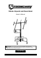
50-Lb. Drywall and Panel Hoist Owner’s Manual WARNING: Read carefully and understand all ASSEMBLY AND OPERATION INSTRUCTIONS before operating. Failure to follow the safety rules and other basic safety precautions may result in serious personal injury.
Thank you very much for choosing a Strongway™ product! For future reference, please complete the owner’s record below: Serial Number/Lot Date Code: ________________________________ Purchase Date: ____________________________________________ Save the receipt, warranty, and this manual. It is important that you read the entire manual to become familiar with this product before you begin using it. This hoist is designed for certain applications only.
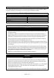
Table of Contents Intended Use .......................................................................................................................................... 4 Technical Specifications ...................................................................................................................... 4 Important Safety Information ............................................................................................................... 4 Specific Operation Warnings .......................
Intended Use The 150-Lb. Drywall and Panel Hoist is a manual tool for lifting panels for ceilings and false ceilings. The gears and pulley system allow you to exert less physical effort when working. Technical Specifications Property Max lift height (ft.) Rotate Max load capacity (lbs.) Casters (in.) Max load size (ft.) Specification 11 360° 150 6 4 x 16 Important Safety Information ⚠WARNING Read and understand all instructions.
and contact will cause electrical shock. Keep children and bystanders away from the work area while operating the tool. Do not allow children to handle the product. Be aware of all power lines, electrical circuits, water pipes, and other mechanical hazards in your work area. Some of these hazards may be hidden from your view and may cause personal injury and/or property damage if contacted.
Inspect the tool for good working condition prior to storage and before re-use. Use only accessories that are recommended by the manufacturer for use with your product. Accessories that may be suitable for one product may create a risk of injury when used with another tool. Never use an accessory that has a lower operating speed or operating pressure than the tool itself. Keep guards in place and in working order. Never operate the product without the guards in place.
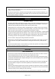
Assembly Instructions 1. Install the two shelves onto the cradle with a butterfly nut. 2. Install the two side shelves on the shelves with butterfly nut.
3. Expand the central pieces on the floor. 4. Bring the legs into position.
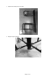
5. Lock the legs with the appropriate hooks. 6. Lock the footboard onto the rack with a screw.
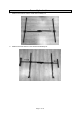
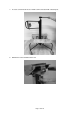
7. Insert the control handle into the middle column and attach with a butterfly nut. 8. Release the control handle from the unit.
9. Once the control handle is detached from the unit, hold the handle tightly and you can enter the cradle.
Operating Instructions ⚠WARNING Wear ANSI Z87.1 compliant safety goggles, hard hat, heavy duty gloves, and steel toed boots during setup and use. Do not exceed the rated load capacity. Do not use to transport people or pets. Secure load before raising or lowering load. Only use the hoist to raise and lower one panel at a time. Never load a drywall panel or operate the hoist if the lock pins are not engaged at one of the three positions. Use ONLY for lifting a drywall panel.
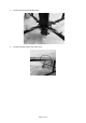
2. Place the board on the extension of the cradle. 3. Pull the control handle down to the horizontal position.
4. To raise the cradle by turning the rotating crank, turn the handle clockwise, keeping the other hand firmly on the handlebars. Lift up to the desired height with the desired direction. Now the board can be attached to the ceiling. Maintenance Maintain the product by adopting a program of conscientious repair and maintenance in accordance with the following recommended procedures. It is recommended that the general condition of any tool be examined before it is used. Keep your tool in good repair.
Troubleshooting Use the table below to troubleshoot problems before contacting service personnel or your local dealer. If the problem continues after troubleshooting, call your local dealer for assistance. Failure The drywall is unable to move. Possible Cause Corrective Action The castors’ brakes are locked. Release the castors’ brakes. The locking device is open as shown. Check the locking device and lock it as shown. The control handle is locked as shown. Release the control handle.
Parts Diagram Page 16 of 19
Parts List Reference 1 2 3 4 5 6 7 8 9 10 11 12 13 14 15 16 17 18 19 20 21 22 23 24 25 26 27 28 Part Number 1 2 3 4 5 6 7 8 9 10 11 12 13 14 15 16 17 18 19 20 21 22 23 24 25 26 27 28 Part Description Box Security clamp Metal rope Adjustable extension Shelf Side shelf Cradle Rubber support kit Butterfly nut Plastic support kit Control handle V shape linking pole (1) V shape linking pole (2) Central column Pin Pulley Spring washer Crank set Gear set Compound board Bolt with nut Castor with brake Castor with
Limited Warranty Northern Tool and Equipment Company, Inc. ("We'' or "Us'') warrants to the original purchaser only ("You'' or "Your") that the Strongway product purchased will be free from material defects in both materials and workmanship, normal wear and tear excepted, for a period of one year from date of purchase. The foregoing warranty is valid only if the installation and use of the product is strictly in accordance with product instructions.
Distributed by: Northern Tool & Equipment Company, Inc. Burnsville, Minnesota 55306 www.northerntool.