48in. Dethatcher Owner’s Manual WARNING: Read carefully and understand all ASSEMBLY AND OPERATION INSTRUCTIONS before operating. Failure to follow the safety rules and other basic safety precautions may result in serious personal injury.
Thank you very much for choosing a Strongway product! For future reference, please complete the owner’s record below: Serial Number/Lot Date Code: ________________________________ Purchase Date: ____________________________________________ Save the receipt, the warranty, and this manual. It is important that you read the entire manual to become familiar with this product before you begin using it. This 40” Dethatcher is designed for certain applications only.
Table of Contents Intended Use .......................................................................................................................................... 4 Technical Specifications ...................................................................................................................... 4 Important Safety Information ............................................................................................................... 4 Specific Operation Warnings .......................
Intended Use This tow-behind 40” Dethatcher helps prevent roots, leaves, grass clippings, and other small vegetation from inhibiting the growth of your lawn. The Dethatcher has 20 oil-tempered, spring tines that comb the matter layer of thatch onto the surface where it can be easily bagged or mulched. Technical Specifications Property Working width Tires Construction Hitch style Specification 48” 7” Poly Steel Pin-style Important Safety Information Read and understand all instructions.
PERSONAL SAFETY Stay alert, watch what you are doing, and use common sense when operating the tool. Do not use the tool while you are tired or under the influence of drugs, alcohol, or medication. A moment of inattention while operating the tool may result in serious personal injury. Dress properly. Do not wear loose clothing, dangling objects, or jewelry. Keep your hair, clothing and gloves away from moving parts. Loose clothes, jewelry, or long hair can be caught in moving parts.
Specific Operation Warnings Lower equipment to ground, stop engine, remove key and set brake before dismounting tractor. DO NOT use if equipment is damaged. Repair equipment before continuing use. DO NOT exceed this implement’s maximum speed of 5 MPH. Exceeding this speed may result in loss of control during transport or braking. Keep seat belt securely fastened while operating. Falling off can result in impalement or being run over.
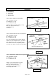
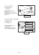
Assembly Tools Required: 2 – 1/2” wrenches 1 – 3/4” wrench 1 – 9/16” wrench 1 – Medium pliers BOLT (19) Step 1: Attach lift plate to main body LIFT PLATE (8) Step 1 Hardware Needed: 4 – Bolt 5/16” x 1” (19) 4 – Lock Nut 5/16” (18) Attach Lift Plate (8) to Main Body (6) using Bolts (19) and Lock Nuts (18). Tighten bolts fully. See Step 1.
Step 4: Attach Hitch Brackets Step 4 Hardware Needed: 2 – Bolt 5/16” x 1-1/4” (22) 2 – Lock Nut 5/16” (18) Attach the Hitch Bracket(2) to the two Hitch Arms(7) using Bolts (22) and Lock Nuts (18). Do not tighten at this point. See Step 4. 5/16”x 1-1/4” Step 4 Step 5: Fully tighten bolts in the following order Step 5 Hardware Needed: 1 – Hitch Pin (23) 1 – Cotter Pin (24) Fully tighten bolts in the order listed below: 1. Front hitch arm bolts in Step 4. 2. Hitch arm bracket bolts in Step 5. 3.
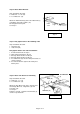
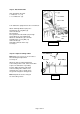
Step 7: Attach the wheels LOCK NUT (13) SHOULDER BOLT (11) Step 7 Hardware Needed: 2 – Shoulder Bolt (11) 2 – Lock Nut (13) Attach each Wheel (5) using a Shoulder Bolt (11) and Lock Nut (13). Tighten the bolts. Note: Only tighten the bolts to the end of the threads. The Wheels (5) need to spin freely on the bolts. See Step 7.
Step 9: Attach lift handle Step 9 Hardware Needed: 3 – Bolt 5/16” x 1” (19) 3 – Lock Nut 5/16” (18) 5/16 x 1” Bolt Turn dethatcher upright onto the tines and wheels. Attach Tall Angle Bracket (25) to the Axle Bracket (9) using Bolt (19) and Lock Nut (18). Do not tighten. Next, position the Lift Handle (10) through the Lift Plate (8) on the Main Body. Attach the Lift Handle (10) to the Tall Angle Bracket (1) using Bolt (19) and Lock Nut (18). Now tighten all bolts in this step. See Step 9.
Before Each Use Check that all connections are tight before each use. Weight may be added to the top of the main body. Secure added weight to the main body. Operating Instructions WARNING: Do not operate this dethatcher above 5 mph. After Each Use Lubricate the wheels and wheel shoulder bolts regularly as needed. Store in a dry place away from moisture or water to avoid rusting. Maintenance Maintain your dethatcher.
Parts Diagram Parts List – Main Body Reference No.
Parts Diagram 11 21 22 15 19 23 24 16 17 14 18 13 20 12 Parts List - Hardware Reference No.
Parts Diagram Parts List Reference No. 1 2 3 5 6 7 8 9 10 11 12 13 Qty. Description Hitch Arm Bracket Hitch Bracket Spring Tine 7” Poly Wheel Main Body Hitch Arm Lift Plate Axle Bracket Lift Handle Shoulder Bolt Short Angle Bracket 2 1 12 2 1 2 1 1 1 2 4 Lock Nut 3/8” 2 Reference No. 14 18 19 20 22 23 24 25 Page 14 of 17 Qty.
Replacement Parts For replacement parts and technical questions, please call Customer Service at 1-800-222-5381. Not all product components are available for replacement. The illustrations provided are a convenient reference to the location and position of parts in the assembly sequence. When ordering parts, the following will be required: Model Number, Serial Number/Lot Date Code, and Description.
Limited Warranty Northern Tool and Equipment Company, Inc. ("We'' or '"Us'') warrants to the original purchaser only ("You'' or “Your”) that the Strongway product purchased will be free from material defects in both materials and workmanship, normal wear and tear excepted, for a period of one year from date of purchase. The foregoing warranty is valid only if the installation and use of the product is strictly in accordance with product instructions.
Distributed by Northern Tool and Equipment Company, Inc. Burnsville, Minnesota 55306 NorthernTool.