48in. Plug Aerator Owner’s Manual WARNING: Read carefully and understand all ASSEMBLY AND OPERATION INSTRUCTIONS before operating. Failure to follow the safety rules and other basic safety precautions may result in serious personal injury.
Thank you very much for choosing a Strongway product! For future reference, please complete the owner’s record below: Serial Number/Lot Date Code: ________________________________ Purchase Date: ____________________________________________ Save the receipt, the warranty, and this manual. It is important that you read the entire manual to become familiar with this product before you begin using it. This 48” Plug Aerator is designed for certain applications only.
Table of Contents Intended Use .......................................................................................................................................... 4 Technical Specifications ...................................................................................................................... 4 Important Safety Information ............................................................................................................... 4 Specific Operation Warnings .......................
Intended Use This 48” Plug Aerator is the perfect aerator for getting water and nutrients to the roots of plants in compacted soil. Technical Specifications Property Aerator Type Spikes (qty.) Spike Length Spike Penetration Depth Working Width Maximum Weight Capacity Specification Plug 32 3” 2.5” 48” 120 lbs. Important Safety Information Read and understand all instructions. Failure to follow all instructions may result in serious injury or property damage.
WORK AREA SAFETY Inspect the work area before each use. Keep work area clean, dry, free of clutter, and well lit. Cluttered, wet, or dark work areas can result in injury. Using the aerator in confined work areas may put you dangerously close to other cutting tools and rotating parts. Do not allow the aerator to come into contact with an electrical source. The tool is not insulated and contact will cause electrical shock.
AERATOR USE AND CARE Do not force the aerator. Products do a better and safer job when used in the manner for which they are designed. Plan your work, and use the correct product for the job. Check for damaged parts before each use. Carefully check that the aerator will operate properly and perform its intended function. Replace damaged or worn parts immediately. Never operate the aerator with a damaged part. Store the aerator when it is not in use.
Specific Operation Warnings CRUSHING AND LACERATION HAZARD Implement is heavy. Be careful when moving or lifting as hands, finders, feet, and other body parts can be crushed. Implement has sharp spikes. Keep hands clear as these spikes can cut. DO NOT exceed this implement’s maximum speed of 5 MPH. Exceeding this speed may result in loss of control during transport or braking. Never allow riders on equipment. Keep bystanders at least 20 feet away while operating.
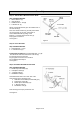
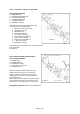
Assembly Step 1: Attach Wheel Bracket to Axle Shaft Step 1 Hardware Needed: 1 – Wheel Bracket (9) 1 – Axle Shaft (6) 1 – Hex Bolt 1/4” x 1-1/2” (B) 1 – Lock Nut 1/4” (T) Wheel Bracke t 5/16” x 1” 1/4” Lock Nut Attach one Wheel Bracket (9) to the middle hole of the Axle Shaft (6). Note: the wheel bracket ring should point toward the shortest side of the axle. See Figure 2. Secure Wheel Bracket (9) using a Hex Bolt 1/4” x 1-1/4” (B) and Lock Nut 1/4" (T). Fully tighten connection. See Figure 2.
Step 4: Assemble Long Side of Axle Shaft Step 4 Hardware Needed: 1 – Middle Brace (2) 2 – Double Spool Assembly (10) 1 – 2.11” Spacer Tube (31) 1 – 5.29” Spacer Tube (32) 2 – 1” Spacer Tube (30) 3 – Flat Washer 7/8” (34) 2.11” Long Spacer Assemble below items onto LONG SIDE of the Axle Shaft (6) in the following order: 1. Start with 1” Spacer Tube (30) 2. Flat Washer 7/8” (34) 3. Middle Brace (2) 4. Flat Washer 7/8” (34) 5. 2.11” Spacer Tube (31) 6. Double Spool Assembly (10) 7. 5.29” Spacer Tube (32) 8.
Step 6: Attach Wheel Assembly Step 6 Hardware Needed: 2 – Wheel Assembly (8) 2 – Hex Bolt 1/2” x 4-1/4” (A) 2 – Hex Nut 1/2” (I) 2 – Lock Nut 1/2” (J) Insert Hex Bolt 1/2” x 4-1/4” (A) through Wheel Assembly (8). Install Hex Nut 1/2" (I) on Hex Bolt 1/2” x 4-1/4” (A). Tighten the nut on the bolt (wheel should spin freely). Attach assembled wheel and Hex Bolt 1/2” x 4-1-4” (A) on to wheel bracket and fasten with Lock Nut 1/2” (J). Repeat for the opposite side. Check that wheels spin freely after assembly.
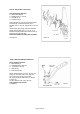
Step 8: Attach Tongue to Top Tray 5/16” x 3/4” Hex Bolt Step 8 Hardware Needed: 4 –Hex Bolt 5/16” x 1-1/4” (C) 2 – Hex Bolt 5/16” x 3/4” (D) 6 – Lock Nut 5/16” (K) 8 – Spacer 1/4” (Q) 5/16” x 11/4”Hex Bolt, 2 – 1/4” Spacers and 5/16” Lock Nut Attach the Tongue (5) to the Top Tray (1) with the large opening of the tray slot facing forward. Attach the Tongue (5) using the top tray holes to the right side of the long slot (viewing from front).
Step 10: Secure Upper Tray Step 10 Hardware Needed: 8 – Hex Bolt 5/16” x 3/4” (D) 8 – Flat Washer 5/16” (M) 8 – Lock Nut 5/16” (K) Figure 10 5/16” x 3/4” Hex Bolt Attach both End Plates (3) to the Top Tray using Hex Bolt 5/16” x 3/4” (D), Flat Washer 5/16” (M), and Lock Nut 5/16” (K) for each corner (2 connections per corner). Repeat for each corner. Do not fully tighten until final step. See Figure 10.
For #2 in Figure 12: Re-straighten end plates, and then fully tighten all 8 corner connections while making sure lift handle still Figure 12 moves freely. Tighten Middle Brace and Top Tray connections from Step 9 and 10. CHECK THAT ALL CONNECTIONS ARE TIGHT. Figure 12 BEHIND THE LIFT ARM on the top tray is a place for Lock Pin (F) device. Slide Lock Pin through holes when Aerator is in the upright position.
Parts Diagram Page 14 of 19
Parts List Reference No. 1 2 3 4 5 6 7 8 9 10 11 12 13 14 15 16 17 19 20 21 22 23 24 25 27 28 29 30 31 32 33 34 Part No.
Parts Diagram Hardware Parts – not actual size Ref. No. Part No.
Replacement Parts For replacement parts and technical questions, please call Customer Service at 1-800-222-5381. Not all product components are available for replacement. The illustrations provided are a convenient reference to the location and position of parts in the assembly sequence. When ordering parts, the following will be required: Model Number, Serial Number/Lot Date Code, and Description.
Limited Warranty Northern Tool and Equipment Company, Inc. ("We'' or '"Us'') warrants to the original purchaser only ("You'' or “Your”) that the Strongway product purchased will be free from material defects in both materials and workmanship, normal wear and tear excepted, for a period of one year from date of purchase. The foregoing warranty is valid only if the installation and use of the product is strictly in accordance with product instructions.
Distributed by Northern Tool and Equipment Company, Inc. Burnsville, Minnesota 55306 NorthernTool.