
Product Manual

Page 10 of 19
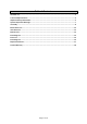
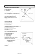
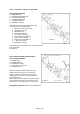
Step 6: Attach Wheel Assembly
Step 6 Hardware Needed:
2
–
Wheel Assembly (8)
2
– Hex Bolt 1/2” x 4
-
1/4” (A)
2
– Hex Nut 1/2” (I)
2
– Lock Nut 1/2” (J)
Insert Hex Bolt 1/2” x 4
-
1/4” (A) through Wheel
Assembly (8). Install Hex Nut 1/2" (I) on
Hex B
olt 1/2” x 4-1/4” (A). Tighten the nut on the
bolt
(wheel should spin freely).
Attach assembled
wheel and Hex Bolt 1/2” x 4-1-4” (A) on to
wheel bracket and fasten with Lock Nut 1/2” (J).
Repeat for the opposite side.
Check that wheels spin freely after assembly.
See Figure 6.
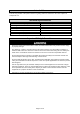
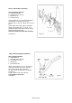
Step 7: Attach Hitch Bracket & Hitch Pin
Step 7 Hardware Needed:
1 – Hitch Bracket (7)
2 – Hex Bolts 5/16” x 3/4” (D)
2 – Lock Nuts 5/16” (K)
1 – Hitch Pin (H)
1 – Hair Cotter Pin (G)
Attach Hitch Bracket (7) to the Tongue (5)
using two Hex Bolt 5/16” x 3/4” (D) and
two Lock Nut 5/16” (K). Insert Hitch
Pin (H) through Hitch Bracket (7) and the
Tongue (5).
Secure with the Hair Cotter Pin (G).
Fully tighten connections
.
See Figure 7.
Figure 6
1/2” Lock Nut
1/2” Hex Nut
1/2” x 4-1/4”
Hex Bolt
5/16” x 3/4”
Hex Bolt
Figure 7