
Product Manual

Page 8 of 19
Assembly
Step 1: Attach Wheel Bracket to Axle Shaft
Step 1 Hardware Needed:
1
–
Wheel Bracket (9)
1
–
Axle Shaft (6)
1
– Hex Bolt 1/4” x 1
-
1/2” (B)
1
– Lock Nut 1/4” (T)
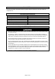
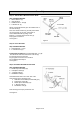
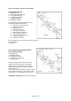
Attach one Wheel Bracket (9) to the middle hole of
the Axle Shaft (6).
Note: the wheel bracket ring should point toward
the shortest side of the axle.
See Figure 2.
Secure Wheel Bracket (9) using a Hex
Bolt 1/4” x 1
-
1/4” (B) and Lock Nut 1/4" (T).
Fully tighten connection.
See Figure 2.
Step 2: Insert Hex Bolt
Step 2 Hardware Needed:
1
– Hex Bolt 5/16” x 1” (E)
1
– Lock Nut 5/16” (K)
Preassembly for Step 11: Insert
Hex Bolt 5/16” x 1” (E)
from the short side of the axle insert Lock Nut (K)
into the hole closest to the axle.
Finger tighten Lock Nut to the Hex Bolt.
Do not tighten until Step 11.
See Figure 2.
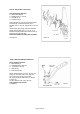
Step 3: Assemble Short Side of Axle Shaft
Step 3 Hardware Needed:
2 – Double Spool Assembly (10)
1 – 5.29 Spacer Tube (U)
1 – 1” Spacer Tube (S)
1 – Flat Washer 7/8” (P)
Assemble below items onto short side of the
Axle Shaft (6) in the following order:
1. Start with one Double Spool Assembly (10)
2. 5.29 Spacer Tube (32)
3. Double Spool Assembly (10)
4. 1” Spacer Tube (S)
5. Flat Washer 7/8” (P)
Note the Plug Knives (15) should face out.
See Figure 3.
1/4” x 1-1/2”
Hex Bolt
Axle Shaft
1/4” Lock Nut
Wheel
Bracke
t
5/16” x 1”
Figure 2
Figure 3