
User's Manual

7
DRAFT
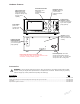
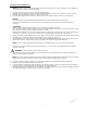
Hardware Features
Color Touch Screen
Display Area; allows
you to view and make
handpiece settings using
its touch screen
capability
Footswitch Connection
Area; allows you to
connect two
footswitches simulta-
neously.
Power Switch;
press to turn
console power
ON and OFF.
Handpiece Connec-
tion Area; allows you
to connect three
handpieces simulta-
neously.
Irrigation Pump
Cassette; install the
irrigation cassette here
if you use the irrigation
pump (optional).
Speaker; provides
audible sounds and
alarms (located inside
console).
Power Receptacle; connect the
console to facility power using the
console power cord. The console will
accept 115 or 230 V facility power.
Irrigation Bag Pole
Mounting Bracket;
connect the pole here if
you use the irrigation
pump (optional).
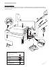
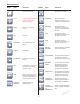
Accessories
WARNING: Use only Stryker approved accessories. Other accessories may not properly interface with the CORE
Console. Contact your Stryker sales representative for a complete list of accessories. DO NOT modify any accessory.
Failure to comply may result in patient and/or operating room staff injury.
Description REF
Power Cord................................................................................................................................................................................. 0996-851-010
Cable; push-pull type connector with alignment markings and keyed connectors .................................................................. 5100-004-000
Footswitch .................................................................................................................................................................................. 5100-008-000
Disposable Irrigation Cassette................................................................................................................................................... 5400-050-001
Enhanced Serial Interface Connectors; three
communication ports allow you to transfer data and control
information, including software upgrades.