
User's Manual

8
DRAFT
Operating Instructions
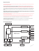
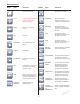
Interconnect Diagram
The interconnect diagram provides the connection sequence of CORE system components. The diagram's numbered callouts
correspond to the numbered instructions on the next page. See the instructions for use supplied with each component for specific
connection information.
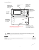
Symbol Definitions
On/Off (push-push)
Footswitch
Handpiece
Irrigation
Type BF Applied Part