
User's Manual

9
DRAFT
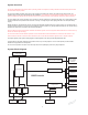
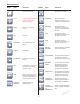
NOTE: Refer to the Interconnect Diagram while performing the instructions below. See the instructions for use supplied with
each component for specific connection information.
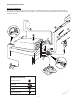
1. Place the console on a sturdy, flat surface near a hospital grade outlet.
2. Install the power cord plug into the power receptacle. Pull the bracket over the plug to secure it within the power receptacle.
3. Install the other end of the power cord into a hospital-grade wall outlet.
4. Press the power switch to turn the console on. See To Power Up and To Adjust Options sections for more information.
NOTES:
• The universal power supply will automatically adjust to match the voltage and frequency of the facility power.
• As you connect components to the console, the console’s screen will change to reflect the various components that are
connected.
CAUTIONS:
• DO NOT thread or twist the push/pull connectors on the cords during installation or removal.
• When connecting or disconnecting a cable(s) to the front of the console, always hold the cable by its connector (the plug, not the
cord). Failure to comply may result in damage to the cable or console.
• Cables that are connected to the front of the console have keyed, push-pull type connectors that lock into place. DO NOT force a
connector into a console port. Each connector and port has an alignment mark to indicate proper cable orientation.
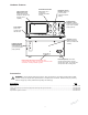
5. If using a footswitch, plug the footswitch cable into the console port marked with a FOOTSWITCH PORT symbol. Align the marks
and gently push the connectors together. Two footswitches may be connected to the console.
6. Plug the handpiece cord(s) into the console port(s) marked with a HANDPIECE PORT symbol. Align the marks and gently push
the connectors together. Three handpieces may be connected to the console and operated simultaneously.
NOTE: If using a CORE Universal Handswitch, attach it to the handpiece before you plug the cord into the handpiece.
7. Plug the other end of the handpiece cord(s) into the handpiece(s). See instructions for use supplied with each handpiece for
connection information.
WARNING: Use only Stryker approved cutting accessories.
8. Attach the cutting accessory to the handpieces. See the instructions for use supplied with each handpiece or attachment for
cutting accessory installation information.
NOTE: If using the console irrigation pump (optional), install the Irrigation Pole REF 5100-50-28 (optional, may use equivalent
irrigation pole) to the mounting bracket on the back of the console. Hang the irrigation bag from the pole.
9. If required, install the irrigation cassette into the console port marked with a IRRIGATION PUMP CASSETTE symbol.
10. If required, connect the irrigation tubing to the irrigation bag.
11. If required, attach the irrigation clips to the handpiece(s) and connect the tubing. Connect the irrigation tubing to the handpiece.
See the instructions for use supplied with each handpiece for connection information.
12. Test all the CORE system components to ensure that they are performing properly before surgery. Refer to the Button Definitions
and Software Menu Map sections when using the graphical user interface.
To Connect the Components: