2/50 CENTRIFUGAL PUMPS FOR DC SUPPLY OPERATING INSTRUCTIONS Please leave this instruction booklet with the pump as it contains maintenance and safety information (Original Instructions)
MODELS 12/50 INDEX . . . . . . . . . . . . . . . . . Page No INDEX . . . . . . . . . . . . . . . . . Page No Application . . . . . . . . . . . . . . . . . . . . . . . . Product Description . . . . . . . . . . . . . . . . . Limits of Application . . . . . . . . . . . . . . . . . Technical Specification . . . . . . . . . . . . . . Siting of the Pump/Pipework . . . . . . . . . . Electrical Installation . . . . . . . . . . . . . . . . Commissioning . . . . . . . . . . . . . . . . . . . . Maintenance . . . .
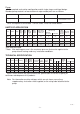
Pump: Close coupled, end suction configuration and of single stage, centrifugal design. Standard pump materials of construction of major wetted parts are as follows: Model Body Impeller Shaft Mechanical Seal 2/50 Brass Acetal or Brass Stainless Steel Nitrile/Carbon Ceramic/Stainless Steel Other seal options are available. Consult Stuart Turner for further details. LIMITS OF APPLICATION Model Impeller Voltage Max. Liquid Temp. o C Min. Liquid Temp. o C Max. Ambient Air Temp o C Max.
SITING OF THE PUMP/PIPEWORK WARNINGS: Pump Location If possible site the pump in a location where in the unlikely event of a liquid leak, any spillage is contained or routed to avoid electrics or areas sensitive to liquid damage. Care should be taken to protect the pump from frost and freezing. Ensure pipework to and from pump is independently supported to prevent stress on the pump inlet and outlet branches.
Lay the suction piping over the shortest possible distance and ensure there is a constant rise from the liquid source to the pump. Any high spots will cause air pockets to form, reducing system efficiency. Ensure all joints in suction pipework are completely airtight. Failure to comply will result in loss of prime. The intake of the footvalve/strainer should be positioned such that it cannot be blocked with debris or silt that are frequently found in the bottom of sumps and wells.
When an alternator or generator is the supply source, ensure correct voltage is available at the motor when pump is operational. Earthing The d.c. supply source to the motor could be from a battery, transformer, altenator or generator, hence there is no requirement or facility for earthing via the supply cable. However certain installations may require additional earthing arrangements to be considered. Static protection & EMC compliance The motor can be connected to earth via it’s front mounting foot.
NOISE The equivalent continuous A-weighted sound pressure level from the pumpset does not exceed 70 dB(A) at a distance of one metre. COMMISSIONING WARNINGS: The motor casing can become very hot under normal operating conditions, care should be taken to ensure it cannot be touched during operation. Do not run pump without terminal/brush guard correctly fitted. The pump chamber must be full of liquid at all times. Seal damage will result if the pump runs dry. 1.
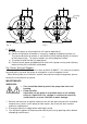
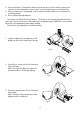
Priming Plug With Priming Plug Without Priming Plug Fig. 2 Fig. 3 5. Starting a) Switch on power to the pump which will now be operational. b) Confirm the direction of rotation is correct by stopping and observing over run. The correct direction of rotation is anticlockwise when looking directly at the front of the pump casing. To reverse rotation see wiring diagram section. c) The pump should now be fully operational.
4. If the installation is fitted with a footvalve and strainer or inline suction strainer, the strainer must be cleaned as necessary to ensure the pump has unrestricted flow. 5. After maintenance is completed, refer to commissioning section for instructions on restarting pump. 6. Brush replacement procedure. The pumps are fitted with brush motors. The brushes will require replacement when worn out.
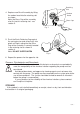
Retaining Slot 4. Replace new Brush Assembly by fitting the carbon head into the retaining slot as shown. Note: the Brass Cap of the assembly also fits into this retaining slot - see section 5. Carbon Head Brass Cap Fig. 7 5. Push the Brush Retaining Cap against the spring tension and screw firmly into place until tight, noting that the Brass Cap of the assembly is correctly located in the retaining slot as shown in section 4. Note: DO NOT OVERTIGHTEN Fig. 8 6.
TROUBLE SHOOTING GUIDE Symptoms Probable Cause Recommended Action Pump will not start. Electrical supply. Check power to motor. Check circuit breaker is set. Check the correct fuse is being used.. Brush gear in need of replacement. Pump runs, but no liquid is pumped. Air locked. Bleed pipework and pump to clear air. No liquid supply. Check the supply valves are turned on. Check outlet not restricted or blocked. Motor running backwards.
DECLARATION OF CONFORMITY 2006/42/EC BS EN ISO 12100-1, BS EN ISO 12100-2, BS EN 809 2004/108/EC BS EN 55014-1, BS EN 55014-2, BS EN 55022, BS EN 61000-3-2, BS EN 61000-3-3, BS EN 61000-4-2, BS EN 61000-4-3, BS EN 61000-4-4, BS EN 61000-4-5, BS EN 61000-4-6, BS EN 61000-4-11 IT IS HEREBY CERTIFIED THAT THE STUART ELECTRIC MOTOR DRIVEN PUMP AS SERIAL NUMBER BELOW, COMPLIES WITH THE ESSENTIAL REQUIREMENTS OF THE ABOVE E.E.C. RELEVANT DIRECTIVES.