
User guide

- 5 -
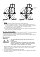
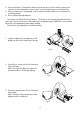
Lay the suction piping over the shortest possible distance and ensure there is a constant
rise from the liquid source to the pump. Any high spots will cause air pockets to form,
reducing system efficiency.
Ensure all joints in suction pipework are completely airtight. Failure to comply will result
in loss of prime.
The intake of the footvalve/strainer should be positioned such that it cannot be blocked
with debris or silt that are frequently found in the bottom of sumps and wells.
When a footvalve is installed on installations that incorporate automatic pump control,
it is recommended that a suitable pressure relief valve be fitted in the discharge (outlet)
pipework from the pump.
ELECTRICAL INSTALLATION
WARNINGS:
The electrical installation must be carried out in accordance with the
current national electrical regulations and installed by a competent
person.
Before starting work on the electrical installation ensure the power
supply is isolated.
This appliance must be earthed.
The motor and wiring must not be exposed to water.
Do not allow the supply cord to contact hot surfaces, including the
motor shell, pump body or pipework. The cord should be safely
routed and secured by cable clips.
The standard pumps are suitable for a supply of 12 volt d.c. or 24 volt d.c. dependent
upon which model selected. Other voltages are available on certain models and it is
therefore very important to ensure the voltage on the pump rating plate matches the
supply.
The motor should be provided with control equipment incorporating means for isolation
of supply and protection against overload, eg: connection via a starter with suitable sized
thermal overload.
The control equipment or starter to which the pump is connected should be mounted in
an easily accessible position and labelled if confusion is possible to allow easy isolation of
the unit.
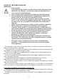
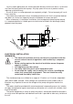
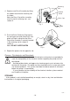
Fig. 1
Outlet
Inlet