Installation, Operation & Maintenance Instructions Please leave this instruction booklet with the owner as it contains important guarantee, maintenance and safety information Read this manual carefully before commencing installation. This manual covers the following products. CH 4-30 FL CH 4-50 FL Pt. No. 46578 Pt. No. 46605 CH 4-40 FL CH 4-60 FL Pt. No. 46596 Pt. No.
PRODUCT DESCRIPTION Electric motor driven centrifugal pump complete with an automatic control system, consisting of flow switch, and electronic control. APPLICATION The Stuart CH FL range is designed for pressure boosting applications in vented stored, hot, cold or blended clean water systems, where under gravity, a flow is available of at least 1 l/min. If you wish to boost both hot and cold services, then CH Boostamatic models must be used, for further details contact ‘PumpAssist’.
CONTENTS Page Checklist . . . . . . . . . . . . . . . . . . . . . . . . . . . . . . . . . . . . . . . . . . . . . . . . . . . . . . . . 4 Important Facts - read before commencing installation . . . . . . . . . . . . . . . . . . . . 5 Location . . . . . . . . . . . . . . . . . . . . . . . . . . . . . . . . . . . . . . . . . . . . . . . . . . . . . . . . 6 Electrical Installation . . . . . . . . . . . . . . . . . . . . . . . . . . . . . . . . . . . . . . . . . . . . . . . 10 Commissioning . . . . . . . . . .
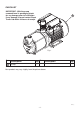
CHECKLIST IMPORTANT: With the pump removed from its packaging check for any damage prior to installation. If any damage is found contact Stuart Turner Ltd within 24 hours of receipt. A Fig. 1 Item Description A Pump Qty Item Description Qty 1 Your product may vary slightly from the picture above. Cont ...
1 READ BEFORE COMMENCING PUMP INSTALLATION A. Water storage capacity. 1.11 The water storage capacity must be sufficient to meet the flow rates required by the pumped equipment and any other water using fittings and appliances, which may be operated simultaneously. 1.12 Ensure the pump is primed as described in the priming section before starting, damage to the shaft seal will result otherwise. See Section 4 - Commissioning. B. Water temperature The water entering the pump must be controlled as follows: 1.
2 LOCATION - GENERAL 2.16 2.17 2.18 2.19 2.20 2.21 2.22 2.23 2.24 2.11 Access: For emergencies and maintenance the pump must be easily accessible. 2.12 Protection: The pump must be located in a dry position, frost free and protected from freezing, particularly when installed in a loft (not recommended). 2.13 Ventilation: Ensure an adequate air flow to cool the pump. Separate the pump from other appliances that generate heat. An 80 mm (3 “) air gap must be maintained around the pump. 2.
Static outlet pressure 12 m Static inlet pressure Min. 1 m Max. 10 m 2 LOCATION - COLD WATER INSTALLATION Cold water pump Fig. 2 2.25 The cold water supply: The supply must be AIR FREE and have a DEDICATED CONNECTION to the tank which should be via a tank connector, positioned at a slightly lower level (25 mm minimum) than the feed pipe to the hot water cylinder. Cont ...
Static outlet pressure 12 m LOCATION - HOT WATER INSTALLATION Static inlet pressure Min. 1 m Max. 10 m 2 Hot water pump Fig. 3 Hot water connection: 2.26 Hot water cylinder or storage tank: When a hot water cylinder or storage tank is used, ensure the pipework size from the cold water storage to the hot water storage is of adequate size and a minimum of 28 mm. 2.
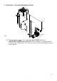
hot water services Fig. 5 350 mm min Least preferred area Max. inlet head 10 m Min. inlet head 1 m 200 mm min 2.29 Non-Preferred Pump Location: The pump must be located with at least 1 metre flooded suction at all times. If it is not possible to locate the pump in the preferred area due to site limitations and it is necessary to position the unit in the loft, or in a position above the secondary tapping that feeds the pump, then there is an increased risk of air locks. This risk must be eliminated.
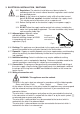
3 ELECTRICAL INSTALLATION / EARTHING 3.11 Regulations: The electrical installation must be carried out in accordance with the current national electrical regulations and installed by a qualified person. 3.12 Safety: In the interests of electrical safety a 30 mA residual current device (R.C.D. not supplied) should be installed in the supply circuit. This may be part of a consumer unit or a separate unit. 3.13 Before starting work on the electrical supply ensure power supply is isolated. 3.
3.21 Wiring Diagram: GREEN / YELLOW (LINK WIRE) CAPACITOR BLACK N L GREEN / YELLOW RED YELLOW RED A M BLUE BROWN BLACK RED MOTOR N 230 VAC/1PH/50Hz L SUPPLY E N FLOWSWITCH REED (S3) S1 S2 S3 S3 S2 S1 PRESSURE SWITCH (S1) All models Fig. 7 3.22 Fuses: The following fuse size should be used with the appropriate pump: Model Fuse Size (AMPS) All Models 13 3.
4 COMMISSIONING / SYSTEM FLUSHING/ PRIMING / STARTING 4.11 System Flushing: The pipework system should be flushed out prior to the pump being connected to ensure any contaminants/ chemical residues and foreign bodies are removed from elsewhere in the system. 4.12 Water Supply: Always ensure that water storage capacity is adequate to meet the demand. Ensure the pump chamber is full of water before starting the pump. Failure to do this could result in seal damage.
5 MAINTENANCE 5.11 Cleaners, Disinfectants and Descalents: Acid based descalents and aggressive cleaning agents must not come into contact with the pump. The pump must be removed from the system prior to the use of these products. The system should be flushed to remove all chemicals before the pump is re-connected. If in any doubt as to the suitability of the chemical solutions, please contact our PumpAssist helpline on 0844 98 000 97. Cont ...
6 TECHNICAL SPECIFICATION Materials Pump Dimensions Mechanical Electrical Model CH 4-30 FL CH 4-40 FL CH 4-50 FL CH 4-60 FL Power supply Volts/phase frequency 230/1/50 230/1/50 230/1/50 230/1/50 Enclosure IPX5 IPX5 IPX5 IPX5 Type of motor Induction Induction Induction Induction Power consumption 805 Watts 1210 Watts 1640 Watts 1980 Watts Full load current 3.6 Amps 5.4 Amps 7.3 Amps 8.8 Amps Rating Continuous (S1) Continuous (S1) Continuous (S1) Continuous (S1) Max.
7 TROUBLE SHOOTING GUIDE Symptoms Probable Cause Recommended Action Pump will not start. Electrical supply. Check power supply. Check fuse (see fuse section). Check circuit breaker is set. Check wiring connections. Pump Jammed. If motor ‘Buzzes’ switch off power and contact Stuart Turner. Recommended static inlet/outlet heads exceeded. Re-position pump (see pump location section). No flow. Insufficient gravity flow to start the pump (must be at least 1 l/min. Internal motor thermotrip activated.
7.11 Flow Switch Circuit Test: 1. First confirm visually that the flow switch reed clamp have not been dislodged during handling or installation. The clamp must be fully located within the flow switch body groove as shown. 2. To carry out the following test you will need to obtain a magnet, a typical fridge magnet is suitable. 3. Ensure the power supply is switched on. 4. Position the magnet directly in front of the reed clamp as shown.
8 YOUR 1 YEAR GUARANTEE Stuart Pumps are guaranteed by Stuart Turner Limited to be free from defects in materials or workmanship and the guarantee period starts from the date of purchase or date of manufacture. Within the guarantee period we will repair, free of charge, any defects in the pump resulting from faults in material or workmanship, repairing, exchanging parts or exchanging the whole unit as we may reasonably decide.
NOTES - 18 -
NOTES - 19 -
DECLARATION OF CONFORMITY 2006/42/EC BS EN ISO 12100-1, BS EN ISO 12100-2, BS EN 809 2006/95/EC BS EN 60335-1, BS EN 60335-2-41 2004/108/EC BS EN 55014-1, BS EN 55014-2, BS EN 55022, BS EN 61000-3-2, BS EN 61000-3-3, BS EN 61000-4-2, BS EN 61000-4-3, BS EN 61000-4-4, BS EN 61000-4-5, BS EN 61000-4-6, BS EN 61000-4-11 1999/519/EC BS EN 62233 2011/65/EU IT IS HEREBY CERTIFIED THAT THE STUART ELECTRIC MOTOR DRIVEN PUMP AS SERIAL NUMBER BELOW, COMPLIES WITH THE ESSENTIAL REQUIREMENTS OF THE ABOVE E.E.C.