Installation, Operation & Maintenance Instructions Please leave this instruction booklet with the home owner as it contains important guarantee, maintenance and safety information Read this manual carefully before commencing installation. This manual covers the following products: Turbo 20S Turbo 15T Pt. No. 49052 Pt. No. 49031 Turbo 30S Turbo 20T Pt. No. 46053 Pt. No. 49032 Turbo 30T Pt. No.
PRODUCT DESCRIPTION Electric motor driven single or twin ended peripheral pump, complete with an automatic control system, consisting of flow switches and electronic controls. APPLICATION Techflow Positive head pumps are suitable for positive head installation conditions. The pumps are designed for pressure boosting applications in vented stored hot or cold, clean fresh water systems, where under gravity, some flow (approx. 0.6 l/min) is available.
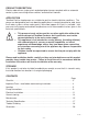
CHECKLIST B B C C A Fig. 1 Item Description Qty Item Description A Pump 1 B Hose 2 C Hose with isolating valve Qty 2 Your product may vary slightly from the picture above. Cont ...
1 READ BEFORE COMMENCING PUMP INSTALLATION A. Water storage capacity. 1.11 The hot and cold water storage capacity must be sufficient to meet the flow rates required by the pumped equipment and any other water using fittings and appliances, which may be operated simultaneously. 1.12 Ensure the pump is primed as described in the priming section before starting, damage to the shaft seal will result otherwise. See Section 5 - Commissioning. B.
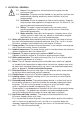
2 LOCATION - GENERAL 2.16 2.17 2.18 2.19 2.20 2.21 2.22 2.23 2.24 2.25 2.26 2.11 Access: For emergencies and maintenance the pump must be easily accessible. 2.12 Protection: The pump must be located in a dry position, frost free and protected from freezing, particularly when installed in a loft (not recommended). 2.13 Ventilation: Ensure an adequate air flow to cool the pump. Separate the pump from other appliances that generate heat. An 80 mm (3 “) air gap must be maintained around the pump. 2.
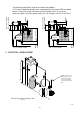
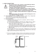
200 mm min least preferred area Max. inlet head 14 m Min. inlet head 0.5 m Fig. 3 (Twin Pump) 350 mm min Fig. 2 (Single Pump) hot water services 350 mm min hot water services least preferred area 200 mm min Max. inlet head 14 m Min. inlet head 0.5 m The following method will help to overcome the problem: A “U” bend or downward loop in the supply pipe to the pump of 350 mm depth before rising to the pump should ensure the cylinder vents its air up the expansion pipe, not up the pump feed (Fig.
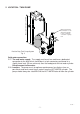
Max. static inlet pressure 14 m 2 LOCATION - TWIN PUMP Outlet head must be below bottom of cold water tank and able to pass a minimum of 0.6 l/min of gravity flow Positive Duty Twin Pump System Fig. 5 Cold water connection: 2.27 The cold water supply: The supply must be air free and have a dedicated connection to the tank which should be via a tank connector, positioned at a slightly lower level (25 mm minimum) than the feed pipe to the hot water cylinder. Do not connect to the mains. 2.
Hot water connection: 2. 29 Hot water cylinder or storage tank: When a hot water cylinder or storage tank is used, ensure the pipework size from the cold water storage to the hot water storage is of adequate size and a minimum of 22 mm for all models. 2.30 Hot water supply: The pump must be supplied with a dedicated feed direct from the hot water cylinder or storage tank. We recommend the use of the Techflow top flange Part No 27901 or side flange 27900. See Section 9 for terms of guarantee. 2.
3 PUMP CONNECTIONS Do not use stainless steel, chrome or nickel plated pipe with the flexible hose push-in plumbing connections. Do not introduce solder flux into the joint or surrounding area as connectors will be attacked and may fail. All solder joints should be completed and flux residues removed before final connection to push-in connections, on the flexible hose.
3. Check in the mouth of the fitting that ‘O’-ring, nylon washer and collet are in position. Collet Body Washer ‘O’-Ring Pipe Stop Isolating Valve Hose Fig. 8 4. Push pipe firmly into fitting, until pencil mark is level with the top of the collet and the pipe stop resistance is felt. Pull on pipe to check it is secure and correctly fitted. 5. To break the joint, push pipe firmly into fitting, hold collet down and gently remove pipe.
4 ELECTRICAL INSTALLATION / EARTHING 4.11 Regulations: The electrical installation must be carried out in accordance with the current national electrical regulations and installed by a qualified person. 4.12 Safety: In the interests of electrical safety a 30 mA residual current device (R.C.D. not supplied) should be installed in the supply circuit. This may be part of a consumer unit or a separate unit. 4.13 Before starting work on the electrical supply ensure power supply is isolated. 4.
The wire which is coloured blue must be connected to the terminal which is marked with the letter N or coloured black. The wire which is coloured brown must be connected to the terminal which is marked with the letter L or coloured red. 4.21 Wiring Diagrams: Parallel wiring of two single pumps is not recommended.
4.24 Cable Gland Fitting Instructions: 1 2 Fig. 13 To enable correct assembly of the cable gland the ‘O’-ring (Fig. 13 item 1) must be placed over the cable before the clamping insert (Fig. 13 item 2) can be tightened. Note: Cable diameter range:- 6.5 mm to 9.5 mm. 4.25 Supply Cord Extension: The pumps are fitted with a supply cord to the following specification:All models . . . . . . . . . . . . . . . . . . HO5VV-F3 G 0.75 mm² - 6 Amp rated cable.
5 COMMISSIONING 5.11 System Flushing: This pump incorporates push-in connectors and plastic components that must not come into contact with solder flux, acid-based descalents or aggressive cleaning agents. The pipework system should be flushed out prior to the pump being connected to ensure any contaminants/chemical residues and foreign bodies are removed from elsewhere in the system. 5.12 Water Supply: Always ensure that water storage capacity is adequate to meet the demand.
6 MAINTENANCE 6.11 Turn off water supplies to the pump and release pressure by opening water outlets before attempting maintenance. 6.12 Inlet strainer: The inlet strainers may require periodical cleaning. The frequency of this operation is dependent upon installation conditions. The strainer is located in the inlet fitting of the pump casing (Fig. 14) and is removed as follows:a) Isolate pump electrically. b) Release all system pressure.
6.15 Cleaners, Disinfectants and Descalents: Acid based descalents and aggressive cleaning agents must not come into contact with the pump. The pump must be removed from the system prior to the use of these products. The system should be flushed to remove all chemicals before the pump is re-connected. If in any doubt as to the suitability of the chemical solutions, please contact the Techflow Technical Helpline on 01444 258017. Cont ...
7 TECHNICAL SPECIFICATION Turbo 15T Dimensions Mechanical Electrical Model Turbo 20T Turbo 30T Turbo 20S Turbo 30S Power supply Volts/phase freqency 230/1/50 230/1/50 230/1/50 230/1/50 230/1/50 Enclosure IPX2 IPX2 IPX2 IPX2 IPX2 Type of motor Induction Induction Induction Induction Induction Power consumption 420 Watts 560 Watts 650 Watts 306 Watts 380 Watts Full load current 2.0 Amps 2.6 Amps 2.9 Amps 1.37 Amps 1.
8 TROUBLE SHOOTING GUIDE Symptoms Probable Cause Recommended Action Pump will not start. Insufficient gravity flow. Check flow rate minimum of 0.6 l/min required on full hot and cold. Electrical. Check power supply. Check fuse (see fuse section). Check circuit breaker is set. Check wiring connections. Pump jammed. If motor ‘Buzzes’ switch off power and contact Techflow Products. Integral motor thermotrip activated.
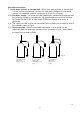
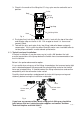
8.11 Flow Switch Circuit Test: 1. First confirm visually that the flow switch reed clamps have not been dislodged during handling or installation. The clamps must be fully located within their flow switch body groove as shown. 2. To carry out the following test you will need to obtain a magnet, a typical fridge magnet is suitable. 3. Ensure the power supply is switched on. 4. Position the magnet directly in front of the reed clamp as shown.
9 THE TECHFLOW GUARANTEE Congratulations on purchasing a Techflow pump. We are confident this pump will provide many years of trouble free service as all our products are manufactured to the very highest standard. All Techflow Pumps are guaranteed to be free from defects in materials or workmanship for 3 years from the date of purchase. EXTEND YOUR PUMP GUARANTEE The guarantee for your Turbo pump will run for a period of 3 years from the date of purchase or date of manufacture, whichever is presented.
This guarantee is in addition to your statutory rights as a consumer. If you are in any doubt as to these rights, please contact your local Trading Standards Department. In the event of a claim please telephone ‘Techflow Technical Helpline’ on 01444 258017 Proof of purchase should accompany the returned unit to avoid delay in investigation and dealing with your claim. You should obtain appropriate insurance cover for any loss or damage which is not covered by Techflow Products in this provision.
NOTES - 22 -
NOTES - 23 -
DECLARATION OF CONFORMITY 2006/42/EC BS EN ISO 12100-1, BS EN ISO 12100-2, BS EN 809 2006/95/EC BS EN 60335-1, BS EN 60335-2-41 2004/108/EC BS EN 55014-1, BS EN 55014-2, BS EN 55022, BS EN 61000-3-2, BS EN 61000-3-3, BS EN 61000-4-2, BS EN 61000-4-3, BS EN 61000-4-4, BS EN 61000-4-5, BS EN 61000-4-6, BS EN 61000-4-11 1999/519/EC BS EN 62233 2011/65/EU IT IS HEREBY CERTIFIED THAT THE TECHFLOW ELECTRIC MOTOR DRIVEN PUMP AS SERIAL NUMBER BELOW, COMPLIES WITH THE ESSENTIAL REQUIREMENTS OF THE ABOVE E.E.C.