STUDER INNOTEC COMPACT User and installer Manual Sine wave Inverter, Battery charger, Transfersystem COMPACT C 1600-12 COMPACT C 2600-24 COMPACT C 4000-48 Temperature sensor CT-35 Remote control RCC-01 Solar charge controller Cxxxx-S Remote power sharing RPS-01 AC cable cover CFC-01 IP-23 top cover C-IP23 User manual COMPACT V4.
STUDER INNOTEC COMPACT Summary 1 GENERAL INFORMATION ............................................................................................................... 4 1.1 1.2 1.3 1.4 1.5 1.6 2 OPERATING INSTRUCTIONS ........................................................................................................................4 QUALITY AND WARRANTY ..........................................................................................................................4 WARRANTY DISCLAIMER.....
STUDER INNOTEC COMPACT 4.7.3 DELAYED MODE OF THE TRANSFER SYSTEM .....................................................................................17 4.8 THE SOLAR CHARGE CONTROLLER (OPTION) ............................................................................................17 4.9 THE MULTIFUNCTIONAL CONTACT ............................................................................................................18 4.10 THE REMOTE CONTROL ......................................................
STUDER INNOTEC COMPACT 1 General Information 1.1 Operating instructions This manual is a part of the delivery package of every COMPACT inverter-charger. It serves as guidelines for safe and efficient operation of COMPACT.
STUDER INNOTEC COMPACT During operation of COMPACT, high tensions are generated at the connections and inside of the appliance which could be deadly fatal. Work on the appliance and on the installation should only be carried out by qualified and trained personnel. The whole installation connected with the COMPACT must comply with the respective valid codes and ordinances.
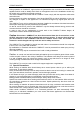
STUDER INNOTEC COMPACT 2 Introduction The COMPACT is a sine wave inverter with integrated battery charger and solar charger controller with many additional functions, it has been developed to be used as stand-alone (independent of a grid-system) AC provider, or as continuous / break-free current supply provider. 2.1 Principle schematic AC IN 1uF L Input 100nF PE 230Vac 10nF PE Output N 10nF Filter 4x2,7MΩ CT35 Temp.
STUDER INNOTEC COMPACT 2.2.4 The solar charge controller (optional) With the built-in solar charge controller, the COMPACT is a complete solar-power-center. In a solar installation this controller ensures that the batteries are charged correctly. With the COMPACT, batteries can be charged with a generator and with the solar modules at the same time. The charging of batteries with both energy sources is carried out fully automatically. 2.2.
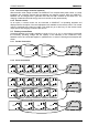
STUDER INNOTEC 2.3.3 COMPACT Parallel- Series Connection 12V 12V 12V 12V C 2600-24 3 Assembly 3.1 Place of assembly The location of the COMPACT must be chosen by the following criteria: Protection from unauthorized handling. Dry dust free room, no condensation. Never install directly over the battery and never in a cabinet together with the batteries. Keep ventilation holes free.
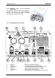
STUDER INNOTEC COMPACT 3.3.2 Protection cover for the terminals connections The protection is available as an option (Order ref. CFC-01) and avoid to do wrong hazardous connection on the terminals 230Vac. It mounted with strain relief clamps for the cable. 3.4 Connecting Plan / Front side M A L O N Caution: Check battery polarity (+/-) before connecting! A wrong connection could damage the system. Don't open before disconnect line and battery BATTERY Remote Power sharing .
STUDER INNOTEC G H Aux. Contact AC Input J K L ID Plate AC Output Caution… M N O Don‘t … 16A Protection Remote Power Sharing COMPACT Connecting terminal for Auxiliary Contact Connecting terminal for AC-input. Located directly above this terminal is the automatic safety cut-out for this terminal. Identification plate with Technical data and Serial number Connecting terminal for AC-output Caution: Check Polarity (+/-) before connecting the battery ! Polarity reversal can damage the COMPACT.
STUDER INNOTEC COMPACT 3.5.4 Connection the 230Vac Input (AC INPUT) The 230V-supply from network or from a generator must be connected to the screw terminals AC INPUT. For this use a 3-core cable with a conductor cross section of 2.5mm2. Connections are marked as follows “N“ Neutral, “PE“ Earth, “L“ Live. 3.5.5 Connect the solar modules: SOLAR +/- (Only for solar option) Solar modules are connected on these terminals. Under no circumstances should any other energy source i.e.
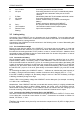
STUDER INNOTEC COMPACT 4 Operating 4.1 Display and operating control elements POWER MONITOR Charge current Cha r g er - I n ver t er CHARGER INPUT LIMIT 16A 0 TRANSFER 0 AC IN 1 CHARGER 2 SOLAR CHARGE 3 22 20W 230V 70A 26 150V 23 [A] 70 60 50 40 30 20 10 STANDBY OFF 24 8 Inverter output power [%] 200 160 130 100 80 60 40 20 10 5 25 AC OUT 7 14 EQUALIZE Program 4 15 Contact active 5 16 Contact manual 6 AUX.
STUDER INNOTEC 4.2 Light Emitting Diodes LED 1 Marking AC IN 2 CHARGER 3 SOLAR CHARGE Program 5 6 7 8 9 10 11 12 13 14 15–18 4.3 19 20 21 4.4 22 23 24 26 LED lit Voltage corresponding to selfadjusted values is at the AC IN input. Battery Charger is working Connected solar modules are delivering energy Programming mode for Aux. Contact Contact active Auxiliary Contact is activated Contact manual Aux. Cont. manually activated Transfersystem is active.
STUDER INNOTEC 4.5 COMPACT The Inverter An Inverter is built in the COMPACT, which generates a sinusoidal alternating voltage of a very high quality. With this Inverter any alternating voltage consuming device 230Vac up to the nominal power of your COMPACT can be operated. Thanks to the generous dimensioning of the COMPACT, you can operate appliances requiring higher power than the nominal power of the COMPACT for a short time. The COMPACT provide up to 3-times the nominal power to start motors.
STUDER INNOTEC COMPACT 4.6 The Battery charger 4.6.1 Cycle of charge The full automatic COMPACT Battery Charger is adjusted at the factory so that most lead-acid and lead-gel batteries can be charged to the maximum. As soon as the minimum alternating voltage for the AC IN set on the Turning Knob 23 is available at the input (LED 1 AC IN is lit), the Battery Charger is switched on automatically (LED 2 CHARGER is lit).
STUDER INNOTEC COMPACT the OUTPUT less it’s give to the charger. Priority to the OUTPUT. When the power sharing is used the LED 200% (red) is lit to point out that’s the charge is limited. Caution: If the power use on the OUTPUT is higher than the value of the INPUT LIMIT (26) the COMPACT limits the current, then the generator means to stop or the circuit breaker before means to break. In option, a remote control (RPS-01, 20m cable) allows the Power Sharing far from the COMPACT. 4.6.3.
STUDER INNOTEC COMPACT The Transfer system is protected against overload with an automatic safety fuse on the AC Input side of the COMPACT. If the system has been overloaded the button/pin of the fuse will pop-out. To put the automatic safety system back in to operating you must push this pin back. Note: In the Inverter operation, The COMPACT generates a true sinusoidal and quartz stabilized output voltage.
STUDER INNOTEC COMPACT 4.9 The Multifunctional Contact In the COMPACT there is a built-in programmable power relay. The potential-free change-over contact (NO – NC) of this power relay is connected to the screw terminal AUX CONTACT. Maximum Contact load: -230Vac /16Amp-30Vdc/1A ! With the Push Button 21 „AUXILIARY CONTACT“ the contact can be manually switched on or off independent of programming and the operating situation. The LED 5 “Contact active” shows the state of the contact.
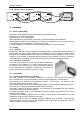
STUDER INNOTEC COMPACT Caution: No external voltage should be connected to this Input Control. 4.11 The Temperature sensor Operating voltage of lead-acid batteries change depends on the temperature. To correct the operating voltages according to the actual temperatures, a temperature sensor can be connected to the COMPACT. The compensation through the sensor is –3mV/°C/Cell. Order Number: CT-35 Dimensions: H x B x T / 58 x 51.5 x 22mm 5 Programming 5.
STUDER INNOTEC COMPACT 5.3.2 Set the voltage and timing threshold The programming is done in accordance with the following steps: Push and hold down, the Push Button 21 (Program) and the Push Button 19 (Change status) for minimum 2 seconds simultaneously. With the Push Button 20 (select) select with of the battery level and the absorption time to be changed.
STUDER INNOTEC 5.4.3 COMPACT Examples 5.4.3.1 Auxiliary Contact as generator starter As per the battery capacity When in the programming of the Auxiliary Contact, the Battery Capacity (LED 15-18) is used as a condition, then you must take note of the following requirements. If you have to start an emergency back-up supply with a battery having a certain residual capacity, then two battery levels must be programmed. The first (i.e.
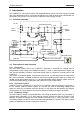
STUDER INNOTEC 5.5.1 COMPACT Diagram of the different modes Show an off LED Show a blinking LED Show a lighted LED 9 AC IN 1 CHARGER 2 AC IN 1 CHARGER 2 AC IN 1 CHARGER 2 AC IN 1 CHARGER 2 7 7 7 7 8 AC OUT 9 INVERTER 8 AC OUT 9 INVERTER 8 AC OUT 9 INVERTER 8 AC OUT 9 INVERTER All the functions are enabled. This is the factory setting. The inverter is disabled. Only the transfer switch and the charger will work normally. Charger and transfer switch are disabled.
STUDER INNOTEC COMPACT 8 Technical Data Technical data Model Inverter Nominal battery voltage Input voltage range Continuous power @ 25°C Power 30 min. @ 25°C Maximum power load 5 sec.