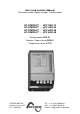
User’s and installer’s Manual Sine wave Inverter, Battery charger, Transfersystem HP-COMPACT HP-COMPACT HP-COMPACT HP-COMPACT - HPC 2800-12 HPC 4400-24 HPC 6000-48 HPC 8000-48 Remote control RCC-01 Remote - Power sharing RPS-01 Temperature sensor CT-35 STUDER INNOTEC Rue des Casernes 57 CH – 1950 Sion TEL : ++41 (0)27 205 60 80 FAX : ++41 (0)27 205 60 88 E-MAIL : info@studer-innotec.
STUDER INNOTEC HP-COMPACT English description .................................................................................................................. 5 1 General Information......................................................................................... 5 1.1 Operating instructions ........................................................................................ 5 1.2 Quality and Warranty .........................................................................................
STUDER INNOTEC HP-COMPACT English description 1 General Information 1.1 Operating instructions This manual is part of the delivery package of every HP-COMPACT inverter-charger. It serves as guidelines for safe and efficient operation of HP-COMPACT.
STUDER INNOTEC 1.4 HP-COMPACT Liability Disclaimer Respecting this manual, servicing and method of installation, functioning, application and maintenance of the appliance can not be controlled or supervised by STUDER INNOTEC.
STUDER INNOTEC HP-COMPACT − Plenty of fresh water and soap must be ready at hand so that in case of acid coming in contact with skin, eyes and clothes, the areas in question can be thoroughly washed. − If acid enters the eyes, you must thoroughly wash them with cold running water for at least 15 minutes. It is recommended that you immediately consult a medical doctor. − Baking powder neutralizes battery acid electrolyte. Always keep some at hand.
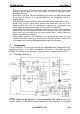
STUDER INNOTEC HP-COMPACT connection between Neutral and earth in inverter mode only may be done by installing a bridge internally to the unit. Please contact your installer regarding this point. (2) Remote control for remote adjustment of the input limit. (see chap. 4.6.3) 2.2 Description of the main functions 2.2.1 The inverter The sine wave inverter HP-COMPACT generates a sinusoidal AC voltage with an exceptionally precise voltage and stabilized frequency.
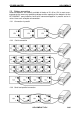
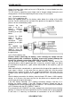
STUDER INNOTEC 2.3 HP-COMPACT Battery connecting Lead-acid batteries are normally available in blocks of 2V, 6V or 12V. In most cases, to generate the necessary operating voltage and the capacity of the batteries for the HP-COMPACT many batteries have to be connected together in parallel and or in series. Here are 3 examples of connection: 2.3.1 Connection in parallel 2.3.2 Serial connection 2.3.3 Serial and parallel connection HP-COMPACT V5.
STUDER INNOTEC HP-COMPACT 3 Mounting and installing 3.1 Installation place The location of the HP-COMPACT must be driven by the following criteria: − Protection from unauthorized handling − Dry dust free room, no condensation − Never install directly over the battery and never in a cabinet together with the batteries − Keep ventilation holes free − In mobile installations it is important to keep the vibrations down as low as possible 3.
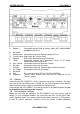
STUDER INNOTEC A B C D E F G H J K L M N 3.5 HP-COMPACT Battery +/- Connection terminal (M8) for battery cable (HPC 4400-24/600048/8000-48 with fuse) Reserved Remote contr. Connection terminal for Remote Control RCC-01 Transfer delay Slide switch for Transfer Delay Equalize Slide switch for equalization of the Battery Temp. Connection terminal for Temperature sensor CT-35 and/or Remote Power Sharing RPS-01 Aux.
STUDER INNOTEC HP-COMPACT charge, the same slide switch can be set in ON position. In case of doubt leave the setting in OFF position. This will allow an equalizing cycle (higher end of charge voltage) during the next charge process. Since then equalizing will occur every 25 usual cycles. 3.6.1 Connection to battery 3.6.1.1 On the appliance side Mount the supplied glands on the battery cable before the setting of the cable terminal. Set the cable terminal and mount the glands on the appliance.
STUDER INNOTEC HP-COMPACT including the battery. If after the fuse replacement and after re-connection of the battery with the right polarity, the HP-COMPACT remains out of order, it must be brought back to your merchant for service. 3.6.2 Connection to the 230Vac-consumer appliances (AC OUTPUT) The 230V consumer appliances must be connected to the terminals AC OUTPUT with cables which cross section has to follow the local rules in force (usually 2.5mm2).
STUDER INNOTEC HP-COMPACT 4 Control 4.1 Display and control parameters HP-COMPACT V5.
STUDER INNOTEC 4.2 HP-COMPACT Light Emitting Diodes (LED) LED 1 Marking AC IN 2 CHARGER 3 Reserved 4 Program 5 6 Contact active Contact manual 7 TRANSFER 8 AC OUT 9 INVERTER 10 Over Temp. 11 Overload 12 Batt. Low/High 13 OFF 14 EQUALIZE 15–18 LED lit Voltage corresponding to self-adjusted values is at the AC IN input. Battery charger is working Program mode for Aux. Contact Auxiliary Contact is activated Aux. Cont. manually activated Transfer system is active.
STUDER INNOTEC 25 4.3 19 20 21 4.4 22 23 24 26 4.5 POWER MONITOR HP-COMPACT Display the value of the output power in % of Pnom (in Inverter Mode) and the charge current in Amps (in Charger Mode). In this mode the red LED indicates that power sharing is in use (>100A). Push buttons Turning the HP-COMPACT on and off (Help Button for Programming) RESET Alarm Signal off (Help Button for Programming) Aux. Contact Control Aux.
STUDER INNOTEC HP-COMPACT time, then it no longer switches on automatically. The LED 13 remains lit. Press the push button 19 „ON/OFF“ in order to switch on the Inverter. 4.5.3 Overheating (Over Temp.) If the Inverter has been overloaded for a long time or it has been working in too high surrounding temperatures, it will switch off. The LED 10 „Over Temp.“ is lit and the LED 13 „OFF“ blinks. After cooling down, the inverter switches back on automatically.
STUDER INNOTEC 4.6 HP-COMPACT The battery charger 4.6.1 Cycle of charge The full automatic HP-COMPACT Battery Charger is adjusted at the factory so that most lead-acid and lead-gel batteries can be charged to the maximum. As soon as the minimum alternating voltage for the AC IN set on the Turning Knob 23 is available at the input (LED 1 AC IN is lit), the Battery Charger is switched on automatically (LED 2 CHARGER is lit).
STUDER INNOTEC HP-COMPACT carried out for 20 minutes (factory setting). During such a charge cycle the LED 14 is lit and during equalizing it is blinking. Charge cycle with equalization can be started independently from the actual program. For this purpose the slide switch must be slid from “OFF” to the “ON” position. The LED 14 will light up. If the periodic equalization is not required, slide switch must be slid back to the „OFF“ position after the completion of the manual cycle.
STUDER INNOTEC HP-COMPACT The measure system built in the HP-COMPACT takes into account the battery voltage, the discharge and charge current as well as the undulation of the voltage. If the battery and the HP-COMPACT are used according to their technical data, the battery state of charge is displayed accurately.
STUDER INNOTEC HP-COMPACT 4.7.1 Set the transfer voltage threshold The voltage threshold of the transfer can be adjusted between 150 to 230V with the turning knobs (23). From factory this value is 200V. Most appliances can work on this voltage. When the Input voltages reach the selected value on turning knob, the inverter switches off and the AC INPUT goes directly on the AC OUTPUT. When the voltage INPUT is less of 20V the value set, the transfer is stopped and the OUTPUT switches back on the inverter.
STUDER INNOTEC − − − − HP-COMPACT Over temperature (LED 10 lit) Overload (LED 11 lit) Over or less voltage of batteries (LED 12 lit or blinking) HP-COMPACT is turned off manually or with a fault (LED 13 lit) In case this function is not wished, it must be modified by programming according to procedure in chap. 5.4. 4.9 The Remote Control RCC-01 As an option, a Remote Control can be connected to the HPCOMPACT.
STUDER INNOTEC HP-COMPACT actual temperatures, a temperature sensor can be connected to the HP-COMPACT. The compensation through the sensor is –3mV/°C/Cell. Order Number: CT-35 Dimensions: H x B x T / 58 x 51.5 x 22mm 4.11 Remote control for „Power Sharing“ RPS-01 If the Remote control RPS-01 is installed, the Trimmer (26) “INPUT LIMIT“ has to be set on the value max.. The HP-COMPACT takes into account the lowest values set on the inverter and on the Remote control.
STUDER INNOTEC 5.2 HP-COMPACT Reset value (default settings) To come back to the default settings, press simultaneously on the push buttons 20/21 during at least 2 seconds. A beep will confirm the comeback to the factory settings. The inverter switches off after this operation. It can be turned on again after the beep. 5.3 Battery voltages and absorption time 5.3.
STUDER INNOTEC HP-COMPACT LED 5.3.2 Table of voltage and timing threshold The voltage levels (low voltage, float charge, end of charge and equalization) and the du-ration of the absorption charge can be changed. The display of these voltages and the times in the program mode are in accordance with the diagram shown below: 14 15 16 17 18 Low voltage Float charge Absorption Equalization LED 13 LED 12 LED 11 LED 10 12 12.0 11.8 11.6 11.4 11.2 24 24.0 23.6 23.2 22.8 22.4 48 48.0 47.2 46.4 45.
STUDER INNOTEC HP-COMPACT like this the Auxiliary Contact works with the lowest set condition and stops when it has reached the highest programmed condition through charging. Example: start of a generator with the HP-COMPACT In order to program the auxiliary contact to start at 25% and to stop at 75% of the battery state-of-charge, here is the procedure to follow: − Press the key AUX. CONTACT (Program) 21 during at least 2 seconds.
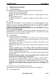
STUDER INNOTEC 5.5 HP-COMPACT Disabling some of the HP-COMPACT functions Each different function charger, inverter and transfer can be disabled. This is useful for specific applications witch required to disable some of these three functions. If you press the buttons 19 and 20 more than 2 seconds you can have access to the different possibilities shown in the following diagram. In programming mode the display shows only the different types of program with the three LED’s 2, 7 and 9 to each function.
STUDER INNOTEC 8 HP-COMPACT Technical Data HP-COMPACT V5.