STUDER INNOTEC SI Sinewave inverter SI SERIES User's and Installer's Handbook STUDER INNOTEC Rue des Casernes 57 CH-1950 Sion Tel : ++41 (0)27 205 60 80 Fax: ++41 (0)27 205 60 88 info@studer-innotec.com www.studer-innotec.com User manual SI V3.
STUDER INNOTEC SI Summary INTRODUCTION ................................................................................................................................ 3 NOTE..................................................................................................................................................... 3 APPLICATIONS AND PERFORMANCE ........................................................................................ 3 PRODUCT PRESENTATION ...........................................
STUDER INNOTEC SI As for the usage of batteries, follow the manufacturer’s instructions. Introduction The SI sinewave inverters have been designed to meet industrial and domestic needs. They satisfy the highest demands of comfort, safety and reliability. Any device designed for the public electrical network of 230V / 50 Hz can be connected to them. The SI inverters are the perfect solution as sources of tension in any place where the public network is not available.
STUDER INNOTEC SI Check the tension and polarity of the battery ! The tension of the battery should coincide with that mentioned in the technical characteristics of the inverter. Battery connection : This connection should done be very carefully observing the polarity in order not to damage the device. Check that the connections are fixed correctly. Assembly Location The place where the inverter is to be mounted should meet the following requirements : Use Out of reach of non authorised persons.
STUDER INNOTEC SI Adjustments These values correspond to a no load situation and they are automatically adjusted according to the current of the battery. (Not automatic with Twinpower version) Standby Level (1) The activation of the inverter, when working in automatic mode, is dictated by the detection of a load. With this function, it is possible to adjust the minimum load detected between 0,3 and 20 Watts. This level is factory adjusted to 2 watts and so no further adjustment will probably be needed.
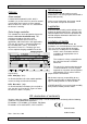
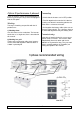
STUDER INNOTEC SI Maintenance Options: The SI inverters do not need any special maintenance. The casing may be cleaned with a damp cloth (not wet). Alarm contact A contact with no potential (0,5A - 60V) is available (12). It warns the user (alarm or control system) when the inverter has been stopped due to a failure or is out of use. It is closed when the inverter is working. Solar charge controller This controller has been designed to charge the batteries with solar installation only.
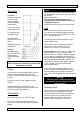
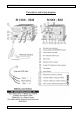
STUDER INNOTEC SI Description and wiring diagram User manual SI V3.
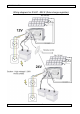
STUDER INNOTEC SI Wiring diagram for SI 600 - 800 S (Solar charge regulator) User manual SI V3.
STUDER INNOTEC SI Option SI performance 3-phased Connecting Three SI inverters can be connected together to build a 3-phased grid. They have to be equipped with the PE option. 1) Check that the inverters are in OFF position. Working Two ways of working are possible with the SI performance : 1) Working alone One SI inverter can be used alone. The inverter works then as a single one, like it is described in this manual.
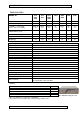
STUDER INNOTEC SI Technical data 612 624 648 812 824 1212 1224 1248 1624 2324 2348 3324 3548 12/24/48 12/24 12/24/48 24 24V/48 24 48 600 800 1200 1600 2300 3300 3500 « Standby » current [mA] Power « ON » no load [W] 25/21/10 2.6 25/21 2.8 25/21/12 4.8 21 5.8 25/17 9 25 13 30 17 Power « ON » no load [W] TWINPOWER system -------- ------- < 0.5 < 0.5 < 0.6 < 0.7 < 0.