User’s and installer’s Manual Sine wave Inverter, Battery charger, Transfersystem XP-COMPACT - XPC 1400-12 XP-COMPACT - XPC 2200-24 XP-COMPACT - XPC 2200-48 Temperature sensor CT-35 Remote control RCC-01 Solar charge regulator Cxxxx-S AC cable cover CFC-01 IP-23 top cover C-IP23 STUDER INNOTEC Rue des Casernes 57 CH – 1950 Sion TEL : ++41 (0)27 205 60 80 FAX : ++41 (0)27 205 60 88 E-MAIL : info@studer-innotec.
STUDER INNOTEC XP-COMPACT English description .................................................................................................................. 5 1 General Information......................................................................................... 5 1.1 Operating instructions ........................................................................................ 5 1.2 Quality and Warranty .........................................................................................
STUDER INNOTEC XP-COMPACT English description 1 General Information 1.1 Operating instructions This manual is part of the delivery package of every XP-COMPACT inverter-charger. It serves as guidelines for safe and efficient operation of XP-COMPACT.
STUDER INNOTEC XP-COMPACT − Damage from atmospheric over voltage (lightning) 1.4 Liability Disclaimer Respecting this manual, servicing and method of installation, functioning, application and maintenance of the appliance can not be controlled or supervised by STUDER INNOTEC.
STUDER INNOTEC XP-COMPACT − Plenty of fresh water and soap must be ready at hand so that in case of acid coming in contact with skin, eyes and clothes, the areas in question can be thoroughly washed. − If acid enters the eyes, you must thoroughly wash them with cold running water for at least 15 minutes. It is recommended that you immediately consult a medical doctor. − Baking powder neutralizes battery acid electrolyte. Always keep some at hand.
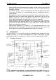
STUDER INNOTEC XP-COMPACT connection between Neutral and earth in inverter mode only may be done by installing a bridge internally to the unit. Please contact your installer regarding this point. (2) Remote control for remote adjustment of the input limit. (see chap. 4.6.3) 2.2 Description of the main functions 2.2.1 The inverter The sine wave inverter XP-COMPACT generates a sinusoidal AC voltage with an exceptionally precise voltage and stabilized frequency.
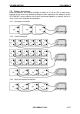
STUDER INNOTEC 2.3 XP-COMPACT Battery connecting Lead-acid batteries are normally available in blocks of 2V, 6V or 12V. In most cases, to generate the necessary operating voltage and the capacity of the batteries for the XP-COMPACT many batteries have to be connected together in parallel and or in series. Here are 3 examples of connection: 2.3.1 Connection in parallel 2.3.2 Serial connection 2.3.3 Serial and parallel connection XP-COMPACT V5.
STUDER INNOTEC XP-COMPACT 3 Mounting and installing 3.1 Installation place The location of the XP-COMPACT must be driven by the following criteria: − Protection from unauthorized handling − Dry dust free room, no condensation − Never install directly over the battery and never in a cabinet together with the batteries − Keep ventilation holes free − In mobile installations it is important to keep the vibrations down as low as possible 3.2 Fixing 3.2.
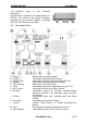
STUDER INNOTEC XP-COMPACT 3.3.2 Protection cover of the terminals connections The protection is available as an option (Order ref. CFC-01) and avoid to do wrong hazardous connection on the terminals 230Vac. It mounted with strain relief clamps for the cable. 3.4 A B C D E F G H Connection Plan Battery +/SOLAR +/Remote contr. Equalize Transfer delay Temp. Aux.
STUDER INNOTEC 3.5 XP-COMPACT Cabling Connecting the XP-COMPACT is a very important step of the installation. You must take care that all connection work is carried out in a clean and correct way and that under no circumstance a cable is connected to a wrong terminal. Connecting of the XP-COMPACT must be carried out in the following order. In case of dismantling this order must be reversed. 3.
STUDER INNOTEC XP-COMPACT 3.6.4 Connect the solar modules: SOLAR +/- (Only for solar option) Solar modules are connected on these terminals. Under no circumstances should any other energy source i.e. wind generator be connected to these terminals! Only solar modules must be connected with two cables +/-. Depending on the power of the modules, the cable cross section should be 2.5 up to 6mm2.
STUDER INNOTEC XP-COMPACT 4.2 Display and control parameters on remote control panel (optional) 4.3 Light Emitting Diodes (LED) LED 1 Marking AC IN 2 CHARGER 3 SOLAR CHARGE 4 Program 5 6 7 Contact active Contact manual TRANSFER 8 AC OUT 9 INVERTER LED lit Voltage corresponding to self-adjusted values is at the AC IN input. Battery charger is working Connected solar modules are delivering energy Program mode for Aux. Contact Auxiliary Contact is activated Aux. Cont.
STUDER INNOTEC 10 Over Temp. 11 Overload 12 Batt. Low/High 13 OFF 14 EQUALIZE 15–18 25 4.4 19 20 21 4.5 POWER MONITOR For the time being the XP-COMPACT is out of service because of overheating. The XP-COMPACT is out of service because of overload or shortcircuit Battery voltage is Battery voltage is or was to high too low XP-COMPACT is XP-COMPACT is for the time being turned off. Turning turned off. Turning it back on will it back on is only follow automatically ! possible manually.
STUDER INNOTEC XP-COMPACT 4.6.1 Charge detection system „Standby“ In order to avoid unnecessary discharge of the battery, the inverter switches OFF automatically if no appliance is connected and switches ON automatically again if appliance is connected. The LED 8 blinks if the inverter is in Standby-Mode. The switching-on/starting level can be adjusted with the turning knob 24 „STANDBY”.
STUDER INNOTEC XP-COMPACT at the input (LED 1 AC IN is lit), the Battery Charger is switched on automatically (LED 2 CHARGER is lit). The battery is fully automatically charged matching to the charge level, the adjusted volt-age levels and the charge current. Thanks to the builtin Float Charge System, the batteries can be left connected for unlimited time with the Battery Charger switched on.
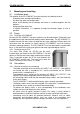
STUDER INNOTEC XP-COMPACT Equalization mode should never be used when using Gel-Batteries. 4.7.4 Charging current The maximum charging current for the battery can be adjusted with the Turning Knob 22 (CHARGER). The charging current of the battery should be set to approximately 10 – 20% of the battery capacity (at C10). This means that the charging current for a battery with 300Ah should be set between 30 – 60A.
STUDER INNOTEC XP-COMPACT lit. The inverter is switched off and the battery charger switched on. This process is automatic, unless the charger mode or the transfer mode is disabled (see Chap. 5.5). The maximum current of the Transfer switch is 16A. That means through this system, consuming devices up to a maximum of al 3700 Watt can be operated. When the Battery Charger is working, part of this power is used for charging according to the power sharing system.
STUDER INNOTEC 4.9 XP-COMPACT The Solar charge controller (option) The XP-COMPACT also has a Solar Charge Controller built in. For charging the batteries, Solar modules can be connected to the screw terminal SOLAR +/-. The inbuilt controller is a „Shunt controller“ for the maximum input current of 30A for XPC 1400-12 and XPC 2200-24 and 20A for XPC 2200-48. The operating voltage of solar panels to be connected must match the actual operating voltage of the XPCOMPACT and never exceeds the max.
STUDER INNOTEC XP-COMPACT 4.11 The Remote Control RCC-01 As an option, a Remote Control can be connected to the XP-COMPACT. All operating controls and displays except from level adjustment are available on the Remote Control. The Remote Control is supplied with a 20m long cable. It can as long as 40m. The Remote Control is suitable for surface mounting on the wall or on to a switch board. It is fixed with 4 screws. The XP-COMPACT can also be programmed with the Remote Control.
STUDER INNOTEC 5 XP-COMPACT Programming (possible only with the remote control RCC-01) The XP-COMPACT (except for 60Hz versions) is equipped with a Flash processor fitted out with EEPROM Memory, which means that even when it is disconnected from the battery, the parameters that were programmed for the application remain after a new connection to the battery. It is possible to reinitialize (RESET) the XP-COMPACT by pressing simultaneously on the three push buttons 19/20/21 during at least 2 seconds.
STUDER INNOTEC XP-COMPACT With the Push Button 19 (Change status) set the desired parameter (voltage or time) to modify (LED 14/ 15/16/17/18). Push Button 19 (Change status) to set the desired value according to the table 5.3.2. If desired, repeat the operation with any other parameter (voltage or time) to be changed. If during 30 seconds no buttons are pressed, the selected values are automatically stored and the XP-COMPACT switches back in to the normal operating status.
STUDER INNOTEC XP-COMPACT are automatically stored and the XP-COMPACT switches back to normal operating condition. 5.4.3 Auxiliary Contact as generator starter As per the battery capacity When in the programming of the Auxiliary Contact, the Battery Capacity (LED 15-18) is used as a condition, you must then take note of the following requirements. If you have to start an emergency back-up supply with a battery having a certain residual capacity, then two battery levels must be programmed. The first (i.e.
STUDER INNOTEC XP-COMPACT The Auxiliary Contact can be operated at any time with the Push Button 21 (AUX. CONTACT). The LED 6 „Contact manual“ lights up as information that the Contact is manually operated, and LED 5 „Contact active“ lights up when the Contact is active. By pushing the Push Button 21 a second time, the Contact is disabled. By pushing it the third time, automatic functions are restored. 5.
STUDER INNOTEC 6 XP-COMPACT Installation Maintenance Apart from the periodic controls mentioned for the connections, the XP-COMPACT does need any maintenance. Keep the appliance clean and from time to time, wipe it clean with a damp cloth. 7 Declaration of CE Compliance Hereby we state that the products described in this user manual comply with the following standards: EN 61000-6-1, EN 61000-6-3, EN 55014, EN 55022, EN 61000-3-2, Dir. 89/336/EEC, LVD 73/23/EEC, EN 50091-2, EN 60950-1.
STUDER INNOTEC 8 XP-COMPACT Technical Data XP-COMPACT V5.