Table of Contents Section Page Introduction 2 Voice Architecture 3 Features and Specs 3 Common Functions 4 Sound Programming / The Sections: Multi / Midi 5, 6 Modulation 7 Programmer 8 Oscillators 8 Filter 9 Filter Control 9 Envelopes 10 Continuous Controller Assignments 11 1
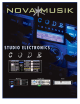
Introduction Welcome to the Studio Electronics Omega series! The world’s first completely programmable discrete analog synthesizer. What to expect Phat, Commanding, Dimension Building, TRUE ANALOG SOUND, in spine tingling stereo. For entire songs worth of processing, use each voice’s auto triggering external input; and each voice capable of having up to four selectable filters, that’s a lot of processing. Just the beginning.
Voice Architecture Discrete Analog Hardware Per Voice Two voltage-controlled oscillators Up to four selectable voltage controlled filters (standard units come with the classic Moog, and four mode Oberheim S.E.M.
Known Bugs We have spent countless hours in designing this instrument to be near perfect in hardware and software operation and we are almost there, but there are a few small bugs that still exist. They should not cause you much trouble, if any, and we have indicated ways to avoid them. 1. Occasionally, after the accu-tune procedure, some of the voices may return in pitch a half step off. The tuning procedure works best when performed in a ROM sound. We have created a special patch for this procedure, B128.
Multi/Midi Knobs volume: master volume control. glide: glide and auto glide rate. Switches Multi Note: to get to multi bank, press and hold bank switch, then press the left arrow switch. set up page 1: select type – prepared, split, layer, or multi. Prepared allows for programming different patches on each voice with midi reception on a single channel. Note: if the first patch in a “prepared” multi patch is a unison patch, the “prepared” multi will be in unison.
glide page 1: [ON] glide on / off, **[TYP] linear or exponential glide response, [MDE] in regular mode glide is active with every key trigger, in legato mode, glide is active only between legato notes, [DST] destinations for glide. page 2: [GLS] glissando or quantized glide on / off, [AUT] auto glide on / off, [INT] auto glide interval, [DYN] dynamic sensitivity to auto glide interval.
Modulation destinations for modwheel, dynamics, and pressure: FRE1 - osc 1 frequency FRE2 - osc 2 frequency 1&2F - osc 1&2 frequency LEV1 - osc 1 level LEV2 - osc 2 level PW1 - osc 1 pulse width PW2 - osc 2 pulse width 1&2P - osc 1&2 pulse width FILT - filter frequency RESO - filter resonance LEVN - noise level XMOD - xmod depth EA1 - envelope 1 amount EA3 - envelope 3 amount EXT - external input mix level LF1R - LFO 1 rate LF2R - LFO2 rate LF1D - LFO 1 depth LF2D - LFO 2 depth 1&2D - LFO
Programmer Knobs Q dial: use for changing patches and editing on screen parameters. Switches left arrow: moves the cursor left. right arrow: moves the cursor right. up down arrows, bank / part: moves the cursor up and down, changes patch banks when the display is on the main page. compare: compares edited patch to programmed patch. exit: returns display to main page. save: saves current patch to same or chosen location. Patches from either bank can be saved to either bank at any location.
Filter Knobs frequency: filter cutoff frequency. resonance: filter resonance level. tracking: filter tracking amount, application of keyboard CV added to filter frequency as you play up the keyboard. Switches edit page 1: [TYPE] filter type selection - Oberheim 12 db low pass, Oberheim 12 db band pass, Oberheim db high pass, Oberheim db band reject, Moog 24db minimoog, AUX1, AUX2 [INVT] inverting of envelopes 1 and 3.
Envelopes Knobs attack x3: attack time, the first stage in the envelope in which the initial rise in filter frequency (env1), volume (env2), or as assigned (env3) rises to peak at the adjusted rate. decay x3: decay time, second stage in the envelope in which peak levels of filter frequency (env1), volume (env2), or assigned (env3) falls from peak to the sustain level. sustain x3: level to which the filter frequency (env1), volume (env2), or assigned (env3) falls to at the end of the decay time.
Current Continuous Controller Assignments # (DECIMAL) * * PARAMETER SENT RECEIVED 54 OSC1 FREQ Y Y 55 OSC1 TRI WAVE ON/OFF Y Y 56 OSC1 SAW WAVE ON/OFF Y Y 57 OSC1 PULSE WAVE ON/OFF Y Y 58 OSC1 SUB OSC ON/OFF Y Y 59 OSC1 PULSE WIDTH Y Y 60 OSC2 FREQ Y Y 61 OSC2 TRI WAVE ON/OFF Y Y 62 OSC2 SAW WAVE ON/OFF Y Y 63 OSC2 PULSE WAVE ON/OFF Y Y 70 OSC2 PULSE WIDTH Y Y 71 LFO1 RATE Y Y 72 LFO1 DEPTH Y Y 73 LFO2 RATE Y Y 74 LFO2 DEPTH Y Y 75 FREQ DOWN (1/2 current value) Y Y 76 ENV 1 UP Y Y 77 INVERT Y Y 78 FREQ