User Guide Issue 1, August 2010 This User Guide is applicable for serial numbers: M47-00151 and later Copyright © 2010 by Studio Technologies, Inc., all rights reserved www.studio-tech.
This page intentionally left blank.
Table of Contents Introduction ................................................................... 5 Installation ..................................................................... 10 Configuration ................................................................ 16 Advanced Configuration ............................................... 17 Operation ...................................................................... 21 Advanced Operation .....................................................
This page intentionally left blank. Issue 1, August 2010 Page 4 Model 47 User Guide Studio Technologies, Inc.
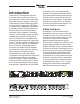
Introduction The Model 47 is designed to interface 2-wire full-duplex party-line intercom circuits with 4-wire audio circuits associated with matrix intercom systems. Other specialized audio system interfacing applications can also be supported. The Model 47 provides two independent full-featured 2-channel interfaces. Each interface contains two hybrid circuits which include automatic nulling capability. The analog circuitry, under software control, provides excellent audio quality and high returnloss.
The Model 47’s 2-wire interfaces can correctly function with powered (“wet”) or unpowered (“dry”) intercom circuits. Powered circuits have a DC voltage present, typically provided by power supplies such as the RTS PS20. This DC power, normally 30-32 volts, provides energy for connected devices such as user stations or belt packs. In this type of application the Model 47 is configured to operate in its external 2-wire power source mode.
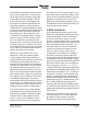
this isolation, technically known as returnloss or trans-hybrid loss, is measured in dB. A high value is important, especially in applications where multiple 2-wire-to4-wire interfaces are used together. Remote sports broadcast applications are especially sensitive to this requirement. The Model 47’s sophisticated auto nulling function uses analog circuitry under microprocessor control to achieve significant trans-hybrid loss.
received from the 4-wire source and two displaying the level being sent to the 4-wire output. During installation and setup the meters are invaluable in helping to confirm that the nominal level DIP switch settings have been properly made. During normal operation the meters offer rapid confirmation of audio signal flow in and out of the unit. Additional LED status indicators are also provided, offering a clear view of the 2-wire DC power and auto null functions.
Simple Installation The Model 47 uses standard 3-pin XLR connectors to allow convenient interconnection in most broadcast and general audio environments. For flexibility, access to the 2-wire party-line intercom interfaces can be made using the connectors provided on both the front and back panels. In permanent installations the back-panel connectors will typically be utilized.
typically connected to 2-wire party-line intercom circuits. But power on both pins 2 and 3 of each interface was necessary for compatibility with SAP panel applications. By adding two DC power sources to each of the Model 47’s 2-wire interfaces, the need for external intercom power supplies could often be eliminated. The final step was to create a physical package that would provide significant resources in a form that allowed simple and reliable integration with other equipment.
4-Wire Line Inputs As previously mentioned, each of the Model 47’s two interfaces allows two analog line-level audio sources to be connected. The source for these signals will typically be ports on a matrix intercom system. It’s also possible that the signals will come from other devices, such as a fiber-optic-based audio transmission system. The 4-wire input circuitry is balanced, capacitor coupled, transformer isolated, and has an impedance of 13 k ohms.
Figure 1. Detail of back panel showing line inputs and outputs 2-Wire Party-Line Intercom Connections wired in parallel (“multed”) and provide access to the identical signals. The Model 47’s 2-wire party-line (PL) intercom interfaces can be directly connected with standard single- and dual-channel party-line intercom devices. But to take advantage of the power that’s provided on both pins 2 and 3 of the PL circuits, the interfaces will typically be routed by way of a source assignment panel (SAP).
Single-Channel Intercom Systems There are two ways of connecting to the Model 47’s 2-wire PL intercom connectors when compatibility with Clear-Com singlechannel intercom devices is desired. The most direct method is to prepare the female XLR mating connector so that common is on pin 1, power is on pin 2, and audio is connected on pin 3. With this connection scenario only audio channel two, associated with pin 3 of the Model 47’s 2-wire PL intercom interface connectors will be utilized.
intercom channels whenever the function is activated. Independent control of sending “mic kill” signals to interface 1 or interface 2 is not supported. User intercom devices compatible with this 24 kHz “mic kill” signal include RTS TW-series belt packs such as the BP325. The opto-coupled remote control inputs are designed for direct connection with 3.3 and 5 volt DC logic signals. An internal 475 ohm resistor, in series with each optocoupler’s photodiode, acts to limit the current flow.
by laying flat between the chassis and the cover. The ribbon cable can then “fan out” to loose wires or, better yet, be terminated onto another connector such as a 9-pin D-subminiature type. A competent technician can easily fabricate an appropriate remote control input interconnect wiring assembly. Starting with a partially pre-made assembly from Digi-Key (part number A1AXH-1036G-ND) makes the task even easier.
Safety Warning: The Model 47 does not contain an AC mains disconnect switch. As such, the AC mains cord plug serves as the disconnection device. Safety considerations require that the plug and associated inlet be easily accessible to allow rapid disconnection of AC mains power should it prove necessary. As soon as AC mains power is applied the Model 47 will begin its power-up sequence. As a “boot up” indication the power LED and each of the status LEDs will momentarily light.
power to pins 2 and 3 of the 2-wire PL intercom connectors. The Model 47 will also provide 200 ohm terminating impedances for both pins 2 and 3 of the party-line connectors. The DC power and termination capabilities allow direct powering of dualchannel intercom belt packs, such as the RTS BP325. In addition, listen-only belt packs, such as the Model 34 from Studio Technologies, Inc. can be directly connected. There’s also no problem connecting single-channel intercom belt packs or user stations.
Figure 6. Detail of back panel showing the Advanced Mode DIP switches Auto Terminate The auto terminate function is designed to ensure that each 2-wire-to-4-wire interface circuit remains stable under most operating conditions. Specifically, 200 ohm impedances are automatically applied to both pins 2 and 3 of a Model 47 2-wire party-line interface when that interface is configured for external power and no external source of intercom power is detected on pins 2 or 3.
The auto terminate function should be disabled only when absolutely necessary; it’s possible that a significant downside could be experienced. With auto terminate disabled it’s important that properly terminated 2-wire party-line intercom circuits be connected to pins 2 or 3 on the Model 47’s 2-wire PL connectors. If they are not connected, it’s likely that audio oscillations, noise, and distortion will be generated in the Model 47’s 2-wire-to-4-wire converter circuitry.
Logic Refresh While testing the Model 46, “cousin” to the Model 47, it was found that in cases of extreme ESD (electro-static-discharge or “static”) an integrated circuit in the audio signal path could “latch up.” This would result in the audio signal no longer passing through this component and on to the 4-wire audio output.
Figure 10. DIP Switch 4—Factory Test in the field DIP switch 4 should remain in its off (down) position. No damage to the Model 47 or connected equipment will occur when factory test mode is active. Operation Technician intervention is typically not required during normal Model 47 operation. The unit is designed for continuous operation with no routine maintenance necessary.
47’s interfaces. If the nominal level is set too low then sufficient audio headroom might not be available. It can also result in excessively high audio signals being sent to 2-wire party-line circuits. Setting the nominal level for too high a value will reduce the signal-to-noise performance. And, as expected, it may also result in audio signals being sent to the 2-wire circuits at too low a level.
External Power Source When set for an external 2-wire power source, the Model 47 will not provide power on pins 2 and 3 of the 2-wire connectors, nor will the Model 47 use any power from a connected intercom circuit. As expected, audio signals will be sent from, and received by, each interface’s two audio circuits. In this mode of operation the Model 47 acts as a typical user station on the connected intercom circuit, albeit without drawing any power.
devices to stabilize. The LEDs associated with pins 2 and 3 will light to indicate that the outputs are active. After this initial 3-second period monitoring becomes active. A fault condition is detected if the power on a pin falls below 24 volts for a continuous 1-second interval. The hardware and software responds to this condition by turning off the power source on that specific pin and flashing its associated LED as a warning.
selected. If DIP switch 2 is in its on (up) position, the front-panel pushbuttons will function in quite a different manner. In the independent mode, a single tap to a button will cause channel 1 to auto null. Two taps will cause channel 2 to auto null. By observing the operation of the two auto null status LEDs it will become readily apparent which of the button modes has been selected.
circuits to generate a very impolite noise. This condition, caused by the 2-wire output circuitry being in an “unloaded” state, will not damage the Model 47’s circuitry. But errors in cable “patching,” a disconnected cable, or other real-world issues can lead listeners of the Model 47’s 4-wire outputs from being presented with a rude surprise! In conclusion, it’s important that technical personnel working with the Model 47 be informed when the auto termination function has been disabled.
Interface 1 LED Section (Major Release Number) Interface 2 LED Section (Release Sub-Number) O 4 .4 O O 3 .3 O 2 .2 O 1 .1 O Figure 12. Detail of front panel showing the status LEDs that display the software version. In this example, the software version is 1.3. FLASH memory. This non-volatile memory is used to store the operating software (“firmware”). Re-programming this memory requires using a specialized programming unit.
Model 72 Interface And now for a shameless “product plug.” Studio Technologies, Inc. manufactures a nifty product called the Model 72 Level Meter/Interface. A compact, standalone unit, it can prove very useful when setting up, maintaining, and troubleshooting intercom circuits. It will give a direct indication of signal levels at any point in a single- or dual-channel intercom circuit. Check it out! Specifications General Audio: Frequency Response: ±2 dB 100 Hz to 8 kHz Distortion (THD+N): <0.
Appendix A Interfacing RTS® Matrix Intercom Systems with the Model 47 Interface ADAM™ Matrix Intercom System Analog Ports to Model 47 Interface RVON-I/O I/O Connections to Model 47 Interface Model 47 User Guide Studio Technologies, Inc.
Appendix B Interfacing Riedel® Artist™ Matrix Intercom System Analog Ports with the Model 47 Interface Issue 1, August 2010 Page 30 Model 47 User Guide Studio Technologies, Inc.
Appendix C Interfacing Clear-Com® Matrix Intercom System Analog Ports with the Model 47 Interface Model 47 User Guide Studio Technologies, Inc.