Model 5401A Dante® Leader Clock User Guide Issue 2, July 2021 This User Guide is applicable for serial numbers M5401A-01001 and later with Main MCU Firmware 1.04 and later Copyright © 2021 by Studio Technologies, Inc., all rights reserved studio-tech.
This page intentionally left blank.
Table of Contents Revision History ................................................................................................................. 4 Introduction ......................................................................................................................... 5 Installation .......................................................................................................................... 9 Dante Configuration ..................................................................
Revision History Issue 2, July 2021: • Documents support for 176.4 and 192 kHz sample rates. • Miscellaneous corrections and clarifications. Issue 1, May 2021: • Initial release. Issue 2, July 2021 Page 4 Model 5401A User Guide Studio Technologies, Inc.
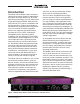
Introduction The Model 5401A Dante Leader Clock provides precise timing signals for applications that utilize the Dante audio-over-IP media networking technology. The unit implements a high-performance IEEE® 1588 precision time protocol (PTP) server, compatible with the requirements of Dante and capable of simultaneously supporting the timing needs of up to hundreds of Dante-compatible devices. As expected, the Model 5401A provides the PTPv1 (IEEE 1588-2002) compatibility that’s required by Dante.
Applications Applications for the Model 5401A include broadcast and post-production facilities, college and university audio networks, arenas, stadiums, corporate installations, and virtually any application where substantial numbers of Dante-compatible devices are utilized. The Model 5401A will serve as a stable and consistent Leader clock for the entire Dante “network.” And, as expected, the Model 5401A is compatible with all Dante devices, no matter what their function or manufacturer.
5401A’s logic circuitry to create the highly stable word clock output. This ensures that the word clock output is synchronized with the unit’s PTPv1 and PTPv2 server functionality. Audio Tone Generator The Model 5401A generates eight sine wave audio tones intended for general-purpose use. These audio tones are available from the Model 5401A by way of Dante transmitter (output) channels and can be connected, using the Dante Controller application, to Dante receivers (inputs) on related equipment.
interconnections are made, the Model 5401A will perform its tasks without risk of interruption due to conflicting resource demands. Flexible Networking Capability Using the Dante Controller application program, the Model 5401A’s three Ethernet ports can be selected to operate in one of four modes: Switched, Redundant, Switched+Mgmt, and Redundant+Mgmt. This should allow virtually any desired networking implementation to be easily achieved.
Installation In this section the Model 5401A will be mounted in one space (1U) of an equipment rack. In many cases, an external synchronization source will be connected to the sync input BNC jack. If needed, a connection may be made to the word clock output BNC jack on the back panel. One or more Ethernet data connections will be made. AC mains and/or DC power will be connected to the Model 5401A.
A source of bi-level or tri-level video can also be connected to the sync input. Circuitry within the Model 5401A will decode many of the common video rates and formats, allowing them to serve as a timing reference. Refer to Appendix A, located at the end of this guide, for a list of compatible rates and formats. If the sync input is configured for video and termination has been enabled an impedance of 75 ohms will be applied. A source of 10 MHz sine wave can be connected to the Model 5401A’s sync input.
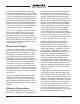
Model 5401A Ethernet Port Dante Controller Network Switch Configuration Pri Sec Switched Dante Redundant Dante Primary Switched+Mgmt Redundant+Mgmt Management Dante Secondary Dante and Management Dante Primary and Management Mgmt Dante Secondary Management Disabled Disabled Figure 2. Model 5401A Ethernet Port Configuration and Operation Connections to the three Ethernet interfaces are made by way of standard RJ45 jacks that are located on the back of the Model 5401A’s enclosure.
Connecting Power The Model 5401A requires a source of AC mains or nominal 12 volts DC for operation. Either source can be connected with the same result. Both can also be simultaneously connected if a redundant (backup) power scheme is desired. Connecting AC Mains Power The Model 5401A can operate directly from AC mains power of 100 to 240 volts, 50/60 Hz, 5 watts maximum. As a “universal mains input” device there are no switches to set or jumpers to install.
The Model 5401A’s Dante interface is compatible with the Dante Domain Manager (DDM) software application. Refer to DDM documentation, also available from Audinate, for details on which Model 5401A and related parameters may have to be configured. Audio Routing The Model 5401A’s eight Dante transmitter (output) channels can be assigned to the desired Dante receiver (input) channels on associated equipment. This will route the eight channels associated with the tone generator function.
If the Model 5401A’s Dante network is configured for Switched ensure that only one of the two Dante RJ45 jacks on the back panel is connected to the LAN associated with the Dante network. If both of the Model 5401A’s Dante RJ45 jacks are routed to ports on the same LAN this will typically “crash” the network! (Although some of the latest/most-advanced Ethernet switches will automatically detect and prevent such a “network bridging” issue from occurring.
if AES67 mode is enabled then PTPv2 will be utilized and the Dante transmitter (output) channels will use multicast. The sample rate will be fixed at 48 kHz. Preferred Clock Source By the very nature of its intended application, the Model 5401A will normally serve as the Leader Clock for all Dante-enabled devices. The unit has the ability to communicate with the Dante network, selecting itself as the Preferred Leader and causing the Enabled Sync to External function to be enabled.
Accessing the Management Webpages To access the Model 5401A’s home webpage, type the unit’s management IP address into a browser’s search bar. (It’s possible that some browsers may require including the text http:// followed by the IP address.) Of course, the computer associated with the browser must be on the same LAN and subnet as the Model 5401A. Home Menu Once the Model 5401A menu system has been accessed the Home webpage will appear.
are critical to the Model 5401A’s support of related Dante devices. When Internal is selected the Model 5401A’s temperature-stabilized, high-performance crystal oscillator is utilized. This will provide excellent timing accuracy and consistent long-term performance. This source is far superior to that provided by other standard Dante devices. This is the correct choice if a high-quality reference signal is not going to be connected to the sync input.
Force Preferred Leader: This is a configurable field with two choices: Disabled and Enabled. This function impacts how the Model 5401A will control a Dante network’s selection of which device is going to serve as the Leader clock. As the main reason for the Model 5401A’s existence is to serve as a Leader clock, in most applications the unit should be serving in that role. By forcing the Model 5401A to be a Preferred Leader clock it helps to ensure optimal Dante network operation.
5401A’s sync input and is serving as the unit’s timing reference. If Locked (Standby) is displayed this indicates that a valid signal is connected to the Model 5401A’s sync input and while it is capable of serving as the unit’s main timing reference it is not currently serving as the main clock source. If Unlocked is displayed it can be the result of several conditions. It can display if a signal is connected to the Model 5401A’s sync input but is not being recognized as a valid timing reference.
used to provide Dante device timing across different subnets for complex or especially large applications. For more in-depth control of these clocking issues the Dante Domain Manager (DDM) software application can be very useful. Dante Sync Status: The Model 5401A can simultaneously serve as a Leader clock for both Dante primary and Dante secondary networks and is capable of supporting both PTPv1 (IEEE 1588-2002) and PTPv2 (IEEE 1588-2008).
be connected to the Model 5401A by way of a BNC jack that is located on the unit’s back panel. Refer to Appendix E for a view of the Sync Input menu. Lock Status: This is a display-only field that can show Unlocked, Locked followed by one of the word clock rates, Locked followed by one of the video rates, or Locked (10 MHz). It’s also possible that it could display Error which would indicate a Model 5401A hardware problem.
is the sample rate desired for the sine wave audio channels provided by the tone generator function. In most applications this will be 48 kHz. It’s possible that in some audioonly applications 96 kHz or even 192 kHz will be selected. Once the desired sample rate has been selected and/or confirmed, an external word clock source of the same rate should be connected.
wave tones with independent frequency and level configuration. The frequency range is 1 to 22000 hertz (Hz) and the level range is –99 to 0 dBFS. Refer to Appendix E for a view of the Tone Generator menu. The tone signals have Dante transmitter (output) default names of Tone 1 through Tone 8. It’s expected that most applications will only use a few of the tones. But having eight output channels provides flexibility in creating a set of tones with various frequency and level combinations.
ment ports. The Dante primary and management fields will show either Link Down or an IP address. The Dante secondary field will show Disabled, Link Down, or an IP address. Link down will display if an Ethernet connection has not been made to the appropriate RJ45 jack on the Model 5401A’s back panel. Disabled will show if Dante redundancy has not been enabled in the Dante Controller application.
devices. The other RJ45 jack can be used to interconnect with another piece of networked equipment. But having both the Model 5401A’s Dante primary and Dante secondary RJ45 jack routed to ports on the same LAN will typically “crash” the network! Subnet Mask Values: These three fields will show the subnet mask values associated with the Dante primary, Dante secondary, and management ports. They will show either Link Down or a subnet mask value. The subnet mask value will be displayed in dot-decimal notation.
obtaining an IP address in this manner is not successful then the IPv4 link-local protocol will be used. (If an IP address has the format of 169.254.x.x then it was assigned using IPv4 link-local.) Even if the IP address was established using link-local the DHCP protocol will remain active. In this case, approximately every 30 seconds the Model 5401A’s firmware will check for the presence of a DHCP server.
field will not be grayed out and the value can be modified as desired. After entering a revised gateway value, using dotdecimal notation, the Submit button must be pressed for the change to be stored. A system reboot is required for the revised gateway value to be utilized. Restoring the Model 5401A’s default values will not change the stored manual gateway value. Submit: The Submit button is located at the bottom of the Management Interface area of the Network menu webpage.
System Menu This menu has six display-only fields as well as functions that allow the default settings to be restored and the system to be rebooted (restarted). Refer to Appendix E for a view of the System menu. One of the display-only fields shows the hardware serial number and the remaining six provide details about the firmware (embedded software) that is being actively utilized by the Model 5401A. Serial Number: This is a display-only field that shows the Model 5401A’s hardware serial number.
immediately cause the defaults to be restored. Refer to Appendix F for a list of the default values. System Reboot: The Reboot function is located on the bottom of the System menu webpage. It allows the Model 5401A to be rebooted (restarted) without having to perform a power cycle. (The function can be considered to invoke a “cold boot.”) For a system reboot to take place the check box must be enabled prior to pressing the Reboot button. During normal operation a system reboot will never be required.
After the Model 5401A has completed its power-up sequences the unit will begin operation. The eight front-panel LEDs will reflect the real-time status of the unit’s major functions. The front-panel display will allow the viewing of over 20 menu pages showing status and configuration conditions. In addition, using the front-panel pushbutton switches some of the unit’s configuration settings can be revised as required. The following paragraphs will detail the operation of the front-panel LEDs.
whenever a Gigabit or 100 Mb/s Ethernet connection is present and a link has been established. Switched+Mgmt Network Operation PRI LED: The PRI LED will light red when no Ethernet connection is present on the Dante primary or Dante secondary Ethernet ports. It will light green whenever a Gigabit Ethernet connection is present on the Dante primary or Dante secondary Ethernet ports and a link has been established.
The SYNC LED will slowly flash orange if the Model 5401A is serving as the PTPv1 Leader clock for the Dante network and its failover mode is active. This would indicate that the unit was specified to utilize the sync input but is not able to do so. If the SYNC LED is lit solid orange then the Model 5401A is not acting as the PTPv1 Leader clock for the Dante network and the failover mode is active.
RJ45 LED Indicators On the Model 5401A’s back panel there are three RJ45 jacks that are provided for interfacing with the unit’s three Ethernet ports. Two of the ports are typically used for Dante and the third for management functions. The Ethernet ports are labeled Dante PRI, Dante SEC, and MGMT. Associated with each RJ45 jack are two LEDs. One LED is labeled LINK and lights orange when a GigE Ethernet connection has been established with that specific port.
Front-Panel Display Page Descriptions The following sections provide information about the Model 5401A’s front-panel menu pages. Additional details can be found in the Model 5401A Configuration section of this guide. Refer to Appendix D for the menu structure diagram. Row One There are five display pages associated with the top row which we’ll refer to as row one.
connection that is made to either the Dante primary or Dante secondary Ethernet interface. If the network configuration in Dante Controller has been selected for Redundant+Mgmt then the IP address that is displayed will be associated with a connection that is made to the Dante primary Ethernet interface. Current Management Subnet Mask Value: This menu page will show the subnet mask value setting that is active for the management interface and associated web server.
lock icon will show in the upper-right corner of the display. Whenever the IP address configuration is selected for Manual the manual IP address can be modified as desired. This will be indicated by a circle with arrows icon that will show in the upper-right corner of the display. To start the process of changing the manual management IP address press the Enter pushbutton switch on the front panel. An icon with a wrench and screwdriver will display to indicate that an edit is in process.
Dante Primary IP Configuration: This menu page allows the display and revision of the method that the Model 5401A’s Dante interface will use to obtain the Dante primary IP address and related parameters. The choices are Automatic and Manual. This setting has no impact on how the Model 5401A obtains IP addresses for the Dante secondary interface and management interface webpages. An arrow icon will display in the upper-right corner of this menu page. This indicates that the setting can be changed.
Whenever the IP address configuration is selected for Manual the manual Dante primary IP address can be modified as desired. This will be indicated by a circle with arrows icon that will show in the upper-right corner of the display. To start the process of changing the Dante primary IP address press the Enter pushbutton switch on the front panel. An icon with a wrench and screwdriver will display to indicate that an edit is in process.
Reboot Dante: This menu page allows the Dante interface to be rebooted (restarted). This can be useful to force the Model 5401A’s Dante interface to utilize revised Dante primary IP address and related parameter configuration changes. It can also be useful when troubleshooting a Dante network issue. An arrow icon shows in the upper-right corner of the reboot Dante menu. To start the process of rebooting the Dante interface press the Enter pushbutton on the unit’s front panel.
button switches to select the desired action. The choices are to cancel or to confirm. Press the Enter pushbutton switch to select the highlighted action. After performing a system reboot (restart), 20 to 60 seconds may be required for the Model 5401A’s operation to fully restore. During this time period the management Ethernet port will briefly disconnect and then reconnect. Screen Saver A “screen saver” mode will automatically activate two minutes after the last press of a front-panel pushbutton switch.
Dante IP Addresses If the Model 5401A’s Dante interface has been configured in the Dante Controller application for Switched or Switched+Mgmt operation, by default the Model 5401A’s Dante primary Ethernet interfaces will attempt to automatically obtain an IP address and associated settings using DHCP (Dynamic Host Configuration Protocol). If a DHCP server is not detected then an IP address will automatically be assigned using the link-local protocol.
menu structure diagram is available in Appendix D of this guide. It’s also available as a separate document on the Studio Technologies website. By default, the Model 5401A’s management Ethernet interface address configuration is set for automatic. In this way, it will attempt to automatically obtain an IP address and associated settings using DHCP. If a DHCP server is not detected an IP address will automatically be assigned using the link-local protocol in the IPv4 range of 169.254.0.1 to 169.254.255.254.
2. Locate the USB receptacle on the Model 5401A’s back panel. It is labeled Firmware Update. Directly adjacent to the USB receptacle is a small hole that provides visual access to a green LED indicator. few seconds to indicate that a valid file has not been found. After this warning, normal operation using the unit’s existing firmware will begin. 3. Insert the prepared USB flash drive into the USB receptacle.
configuration will be lost. This can be offset in a positive way by returning the Model 5401A to a known configuration, a point that might aid in troubleshooting an issue. Refer to Appendix F for a list of the default values. Lost User Name and/or Password As is covered in detail in other sections of this guide, gaining access to the Model 5401A’s configuration menu webpages requires entering the correct user name and password.
Specifications Applications: High-performance Leader clock for Dante audio-over-IP applications. Also supports AES67-2018 applications. In addition, provides audio tones on Dante transmitter (output) channels for general-purpose use and a word clock synchronization output.
Connectors: Sync Input, Word Clock Output: 2, BNC jack (female connector), per IEC 61169-8 Annex A Ethernet: 3, RJ45 jack USB: type A receptacle (used only for updating firmware) DC Input: 4-pin male XLR (pin 1 negative, pin 4 positive) AC Mains Input: 3-blade male, IEC 320 C14compatible (mates with C13) Environmental: Operating Temperature: 0 to 50 degrees C (32 to 122 degrees F) Storage Temperature: –40 to 70 degrees C (–40 to 158 degrees F) Humidity: 5 to 95%, non-condensing Altitude: not characterized D
Appendix A–Compatible Sync Input Sources The Model 5401A’s external sync input has been tested and confirmed for correct operation with the following signals: Word Clock: Square wave signal with rate of 44.1, 48, 88.2, 96, 176.4, and 192 kHz 10 MHz: Sine wave signal with an amplitude of 1 Vrms, nominal, terminated with 50 ohms Bi-Level and Tri-Level Video: See table below Video Format NTSC (“Black Burst”) PAL (“Black Burst”) 720p/50 Hz 720p/59.94 Hz 720p/60 Hz 1080psf/23.
Appendix B–Network Configuration Examples Issue 2, July 2021 Page 48 Model 5401A User Guide Studio Technologies, Inc.
Model 5401A User Guide Studio Technologies, Inc.
Issue 2, July 2021 Page 50 Model 5401A User Guide Studio Technologies, Inc.
Appendix C–Dante Controller Network Default Configuration Values Dante Interface Default Values: Device Config, Sample Rate: 48k Device Config, Clocking, Unicast Delay Requests: Disabled Device Config, Device Latency: Latency: 1.
Appendix D–Menu Structure Issue 2, July 2021 Page 52 Model 5401A User Guide Studio Technologies, Inc.
Appendix E–Screen Captures Model 5401A User Guide Studio Technologies, Inc.
Issue 2, July 2021 Page 54 Model 5401A User Guide Studio Technologies, Inc.
Model 5401A User Guide Studio Technologies, Inc.
Issue 2, July 2021 Page 56 Model 5401A User Guide Studio Technologies, Inc.
Model 5401A User Guide Studio Technologies, Inc.
Appendix F–Model 5401A Default Configuration Values Main Menu: Main Clock Source: Internal Failover Clock Source: Dante Force Preferred Leader: Enabled Sync Input Menu: Type: Word Clock Termination: On Tone Generator Menu: Tone 1: Frequency 100 Hz, Level –21 dBFS Tone 2: Frequency 200 Hz, Level –22 dBFS Tone 3: Frequency 300 Hz, Level –23 dBFS Tone 4: Frequency 400 Hz, Level –24 dBFS Tone 5: Frequency 500 Hz, Level –25 dBFS Tone 6: Frequency 600 Hz, Level –26 dBFS Tone 7: Frequency 700 Hz, Level –27 dBFS To
Appendix G–PTPv2 (IEEE® 1588-2008) Default Characteristics Notes: 1. For Model 5401A PTPv2 support to be active AES67 compatibility check box must be enabled in Dante Controller application. 2. These default configuration characteristics apply to both the Dante primary and Dante secondary Ethernet interfaces. Domain: 0 Priority 1: 114 Clock Class: 248 Accuracy: Unknown (0xFE) Variance: 61536 Priority 2: 112 Unique ID: 00:1D:C1:XX:XX:XX DSCP: EF (46) Model 5401A User Guide Studio Technologies, Inc.
Appendix H–Accessing the Unit when User Name and/or Password are Not Known Follow this procedure to access the Configuration menu webpages if the user name and/or password is not known. 1. Remove power from the Model 5401A. 2. Press and hold the left arrow and Enter buttons. 3. While continuing to hold the two buttons apply AC Mains or 12 volts DC power. 4. Continue to hold the two buttons and allow the Model 5401A to start.