User Guide Issue 1, September 2007 This User Guide is applicable for serial numbers: M233-00151 and later Copyright © 2007 by Studio Technologies, Inc., all rights reserved www.studio-tech.
This page intentionally left blank.
Table of Contents Introduction ................................................................... 5 System Features ........................................................... 6 Installation and Setup ................................................... 12 Configuration ................................................................ 17 Operation ...................................................................... 28 Advanced Operation .....................................................
This page intentionally left blank. Issue 1, September 2007 Page 4 Model 233 User Guide Studio Technologies, Inc.
Introduction What This User Guide Covers This User Guide is designed to assist you when installing, configuring, and using the Model 233 Announcer’s Console. Additional background technical information is also provided. A product block diagram is included at the end of this guide. System Overview The Model 233 Announcer’s Console is designed to serve as the audio control “hub” for announcers, commentators, and production personnel.
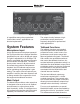
Figure 2. Model 233 back panel of capabilities many other specialized “behind-the-scenes” applications can also be implemented. The output circuitry features a highperformance output transformer expressly designed for professional audio applications. System Features Talkback Functions Microphone Input A high-performance microphone preamplifier circuit provides low-noise/low-distortion amplification over a 20 to 60 dB gain range. The gain is adjustable in 10 dB steps.
main output to be used as an additional talkback output. This feature makes the unit even more powerful when used in liveevent applications, such as serving as a master console for an orchestra conductor or production director. With all the available talkback flexibility, the exact needs of many specific applications can easily be met. And, of course, whatever configuration is implemented, the audio quality will be excellent.
radio broadcasting, announce-booth, or voice-over applications. The fourth mode provides a hybrid function, supporting both push-to-talk and tap-to-enable/tap-todisable operation. This operation is similar to that found in many broadcast intercom system user stations. The two buttons associated with the talkback functions can be configured to operate from either of two modes. One of the modes supports a “push-to-talk” function. This is typically used for on-air broadcast applications.
with satellite transmission systems, are present. In effect the Model 233’s sidetone function adds the “minus” part to a “mix minus” cue. Several configurable parameters allow the sidetone function to be tailored to the needs of a specific Model 233 installation. The sidetone function can be configured to route audio to the left, right, or left and right headphone outputs. It can also be completely disabled.
Intercom Interface Power Sources Of special note is the Model 233’s sophisticated intercom interface. It’s designed to work correctly with industry-standard single- and dual-channel party-line intercom systems, including those from RTS and Clear-Com. An intercom line connected to the Model 233 can serve three functions: providing cue audio signals to the headphone output, allowing talkback audio to be sent to intercom users, and acting as a Model 233 power source.
Configuration Model 233 configurations are made using a number of DIP-type switches and four trim potentiometers. One 8-position switch array is used to set the gain of the microphone preamplifier, the on/off status of phantom power, and control of the headphone output mode. A 12-position switch array configures which of the four cue audio sources, as well as the sidetone audio, are routed to the headphone outputs.
Options The Model 233’s standard resources are more than sufficient to directly support a large number of applications. But in the “real world” of audio and intercommunications special needs always seem to arise. To that end, Studio Technologies offers a number of option cards. In addition to passive or active components, each card contains an integral connector, allowing simple installation into a spare connector location on the Model 233’s back panel.
The selected microphone is interconnected by way of a 3-pin female XLR-type connector which is located on the Model 233’s back panel. The mating connector (male) should be wired so that pin 2 is signal high (+ or hot), pin 3 is signal low (– or cold), and pin 1 is shield. It’s possible that an unbalanced microphone will also work correctly but is not recommended.
Main Output Line-Level Talkback Outputs The Model 233’s main output is intended to be the “on-air” or primary signal that typically connects to the input of an audio console. The output is transformer balanced with a nominal signal level of –2 dBu. The actual level will depend upon the gain setting of the microphone preamplifier, sensitivity of the microphone, and how loudly the user speaks into the microphone. The transformer used in the main output is intended for professional audio applications.
are often part of broadcast and production audio applications. While the output circuitry is not intended to be “on-air” quality, overall audio performance should be very good. Devices connected to the line-level talkback outputs can range from amplified loudspeakers, analog inputs on intercom systems, and input channels associated with audio consoles. Connecting the outputs to devices that allow easy control of the signal level can be helpful.
intercom channels. In addition, the intercom line can provide the DC power required to operate the Model 233’s circuitry. An intercom line is connected to the Model 233 by way of a 3-pin female XLRtype connector which is located on the back panel. The mating connector (male) should be wired so that common is on pin 1, DC with channel 1 audio is on pin 2, and channel 2 audio is on pin 3. With single-channel intercom lines common is on pin 1, DC power is on pin 2, and audio is connected to pin 3.
Pushbutton Labeling The three pushbutton switches used in the Model 233 were selected for several reasons. Foremost was the fact that they are highly reliable, using gold-plated contacts for long life in less-than-ideal environments. A second reason was that applying customized labels to the button caps would be very simple. The labels, text printed on clear material, are placed under the clear caps on the top of the buttons.
Figure 4. Microphone preamplifier gain switch settings Five switches are used to set the gain of the microphone preamplifier. One switch is used to select the on/off status of the phantom power supply. signal up to line level, nominally –2 dBu, on the Model 233’s main output. Operating at this signal level will help to ensure the delivery of “clean” audio to the connected device.
It is visible by observing the bottom of the Model 233’s enclosure when the security plate has been removed. Technically, this red LED lights whenever the compressor circuitry is controlling the dynamic range of the signal coming from the microphone preamplifier. The threshold is set to be 2 dB above the Model 233’s nominal internal operating level.
on the back panel. Two trim pots are associated with the intercom channels. They allow adjustment of the intercom sidetone (null) level. This impacts the amount of talkback audio signal that is returned to a headphone output when a talkback-to-intercom function is active. The sidetone audio source comes from the output of the compressor circuit associated with the microphone preamplifier.
SW2-6, and SW2-9 be placed in their on positions. Note that in some cases a user may wish to wear a headset or a pair of headphones in a left/right orientation opposite of what’s usual. In this situation the transducer designated for the left ear would actually supply audio to the user’s right ear, and vice versa. A specific application where this occurs is when on-air talent needs to have a headset’s boom microphone come across the right side of their face, rather than the more-typical left side.
control, located on the far right, will be used to adjust its level. There is one limitation related to the headphone output mode. It’s the fact that the output will be 2-channel monaural. Whatever signal is present on the headphone output’s left channel will also be present on the right channel. (The exception is if the right-channel output is disabled.) A stereo headphone mix can’t be created. But in most cases this limitation won’t overshadow the benefit of being able to create the mix.
Talkback 1 Button Mode Switch SW3-3 configures how the talkback 1 button functions. Figure 9. Talkback 1 button mode settings Two modes are available: • Push to talk: In this mode the talkback 1 button is normally off. The function becomes active whenever the button is pressed and held. • Hybrid: This mode is a combination of push to talk and alternate action. If the button is pressed and held, the talkback 1 button will become active until the button is released.
Talkback 2 Button Function Switch SW3-6 configures the overall operation of the button associated with talkback 2. Figure 13. Main output source settings Figure 12. Talkback 2 function mode settings Two modes are available: • Disabled: In this mode the talkback 2 button is disabled. The talkback 2 linelevel output and, if configured, talkback to intercom pin 3 function, will never be active. An exception is if the auxiliary relay is configured to follow the status of the talkback 2 button.
Headphone Output Operating Modes The user is provided with three rotary level controls (“pots”) that are associated with the headphone output. Switches SW4-1, SW4-2, and SW4-3 are used to configure the way two of the controls, the one located on the far left and the one located in the center, function. (These settings don’t impact operation of the sidetone level control which is located on the far right.) With just these three switches a wide range of operating modes can be configured.
user is provided with a consistent and easy-to-use set of headphone level controls. Minimum Level Mode Switch SW4-3 is used to configure the minimum headphone output level for the controls located on the far left and center. (This setting doesn’t impact operation of the sidetone level control which is located on the far right.) In the –40 dB mode the minimum output level for the control on the far left and the control in the center is 40 dB below maximum; the outputs will never fully mute.
modes should be considered before a final selection is made. If possible, experimenting with both modes in a test environment might prove to be very helpful. Relay Mode Switch SW4-5 and SW4-6 configure the operating mode of the auxiliary relay. Figure 19. Auxiliary relay control mode settings Four modes are available: • Relay disabled: In this mode the relay is disabled and will never change state. • Follows main output status: In this mode the relay will follow the state of the main output.
of how they impact the Model 233’s operation can lead to many interesting and powerful uses. Talkback to Intercom Functions The last two switches in switch assembly SW2 are used to configure the talkback to intercom functions. Talkback 1 to Intercom Function Mode Switch SW2-11 configures whether the talkback 1 button will allow talkback audio to be sent to pin 2 of the intercom interface. Figure 22.
present on the outputs unless power has been supplied. Specifically, the microphone does not passively “cut through” to the main output connector! Upon Model 233 power up, the four status LEDs will light in succession as a firmware “boot up” indication. The unit will then begin normal operation. Depending on the selected configuration, one LED associated with the state of the main output may be lit. The user is now presented with three buttons, four LEDs, and three rotary controls.
state when talkback began, once talkback activity ends that state will resume; the main output will again be in its on (“latched”) state. Talkback 1 Button and LED Indicator The button in the center, factory labeled TALKBACK 1, controls the function(s) associated with talkback 1. The manner in which the button functions depends on the way it was configured. An LED indicator, green in color, is located directly above the button. It lights whenever talkback 1 is active.
controls to be reversed. A third parameter selects whether the headphone output channels will maintain a minimum output level or can be fully muted. In most cases the headphone output will be configured for stereo, rather than monaural, operation. The following paragraphs will describe how these controls will function in that scenario. Level/Level Mode When set to the level/level mode, the control on the far left and the control in the center operate independently.
When in the level/balance mode and the minimum output level is set to –40 dB, turning the level control to its fully counterclockwise position will place both headphone output channels to 40 dB below maximum. This ensures that talent will never be fully “isolated” from potentially important cue signals. In addition, rotating the balance control to either its fully clockwise or fully counterclockwise position will cause the applicable channel to be 40 dB below its maximum.
one of the talkback outputs is active. The level control on the far right adjusts the side-tone level. When the sidetone level control is in its fully counterclockwise position the sidetone signal will always be fully muted. Astute readers will realize that sidetone audio can also be provided from the intercom cue sources during Model 233 talkback to intercom activity. This “passive” sidetone is created in the intercom interface’s analog talk/listen hybrid sidetone (null) circuit.
to the connected headphones. The user can now, in response to changing conditions, adjust the front-panel level controls as desired. Returning the controls to their detent positions will always provide the “reference” level to the headphone output. A second example has the intercom input and line input 1 both providing cue sources. Pin 2 of the intercom circuit supplies program-with-interrupt audio that is routed to the headphone output’s left channel.
to the user or installer to be connected or disconnected as desired. However repeated field testing found that floating pin 1 on these outputs was the key to maintaining quiet audio. From Fenway Park, to the Orange Bowl, and then northwest to Husker Stadium, lifting pin 1 always did the trick. A simple solution is available if an application does require that a ground be available on the main and line-level talkback outputs’ interconnecting cables.
was very good, limiting the maximum level to at most 10 dB above the nominal. The nominal audio level associated with a Clear-Com system was harder to characterize. It appeared to be a few dB less than –10 dBu, but the dynamic range was much larger. Level peaks of 10 to 20 dB over nominal were easy to produce.
The power supplied by an IFB circuit, normally in the range of 28 to 32 volts DC, is usually sufficient to operate the Model 233’s circuitry. The acceptable input range is 24 to 32 volts, with a required current of 125 milliamperes. Note that the specified input voltage is given when measured directly at the Model 233’s IFB input connector, not at the source of the IFB circuit.
the intercom line, everything worked well. But a new problem arose when it came to finding an external linear power supply for Model 233 users worldwide. For locations that are served by 100 or 120 volts, 60 Hz a 24 volt DC linear “wall-wart” power supply was readily available. This is the power supply that is provided with Model 233 units shipped to North America or Japan.
LED Colors As previously described, two LED indicators are associated with the main output and are located directly above the main output pushbutton switch. The red LED, located on the left, is lit whenever the main output is muted. The green LED, located on the right, is lit whenever the main output is active. The thought process behind the color choices was that red would relate to the main output being muted (“stop”) while green would relate to the main output being active (“go”).
are specifically included so that a Model 233 can be customized to meet the many specific needs that arise in broadcast and related audio applications. Expected uses for these locations include adding a 6- or 7-pin XLR-type connector to allow direct connection of a broadcast headset. Other uses include creating “loop through” or “mult” functions for the line-level talkback output or intercom interface connections. The spare connector locations are compatible with the Neutrik DL-series of connectors.
of the enclosure and two on the back panel, must be removed. A 5/64-inch hex driver is required. The cover can then be carefully separated from the chassis, remaining attached by means of a flexible cable assembly. This “flex-cable” assembly links the main printed circuit board assembly with the board assembly that contains the pushbuttons and LED indicators. Ensure that the flex cable is not damaged while the Model 233 is being customized.
configurations. Note that this is an advanced feature, intended only to be implemented by a qualified technician. From the outset several limitations must be discussed. The first is that button backlighting is not intended to serve tally applications. (A common connection to power all three lamps is provided; independent access to the lamp connections on each button is not provided.) It is strictly intended to provide a moderate amount of illumination to the button’s lens and associated labeling.
P19: Pin 1 is connected to the common point of the Model 233’s circuitry. Pin 2 is connected to the circuitry associated with the main output pushbutton. Pin 3 is connected to circuitry associated with the tally output. An LED indicator lights whenever the compressor’s threshold has been reached and the circuit is actively controlling the dynamic range. This LED is provided as an aid when setting the gain of the microphone preamplifier.
please refer to the Additional Connectors section in the Technical Notes area of this user guide. Specifications General Audio: Frequency Response: 20 Hz-20 kHz, ±0.1 dB, mic in/main out Distortion (THD+N): 0.008%, measured at 1 kHz, mic in/main out S/N Ratio: 80 dB, referenced to –46 dBu mic in/ –2 dBu main out Connectors: Mic In, Line In 1 & 2, Intercom Interface: 3-pin female XLR-type Main Out, Talkback Out 1 & 2: 3-pin male XLR-type Headphone Out: ¼-inch 3-conductor phone jack 24 Vdc Power In: 2.1 x 5.
Appendix A A label is attached to the security plate on the bottom of the unit. It provides a summary of the configurable parameters and related information. The actual label size 4.80 inches by 5.90 inches. Issue 1, September 2007 Page 45 Model 233 User Guide Studio Technologies, Inc.