
Installation Manual


8
MAXIMUM DIRECT VENT, DUAL PIPE LENGTH (FT.)
MG2R INPUTS
(BTU)
INLET / OUTLET
2” DIAMETER
INLET / OUTLET
3” DIAMETER
45,000 30 60
60,000 30 60
72,000 30 60
†
NOTES:
1. Subtract 2.5 ft. for each additional 2 inch long radius elbow, subtract
5ft for each additional 2” short radiious elbow, subtract 3.5 ft. for each
additional 3 inch long radius elbow, and 7 ft. for each additional 3
inch short radius elbow.
2. Two 45 degree elbows are equivalent to one 90 degree elbow.
3. This table applies for elevations from sea level to 2,000 ft. For higher
elevations, decrease pipe lengths by 8% per 1,000 ft of altitude.
Table 2. Vent Pipe Lengths
• The quality of outdoor air must also be considered. Be
sure that the combustion air intake is not located near
a source of solvent fumes or other chemicals which
can cause corrosion of the furnace combustion system.
(See page 5 for a sample list of substances).
• Route piping as direct as possible between the furnace
and the outdoors. Longer vent runs require larger
diameters. Vent piping must be sloped upwards 1/4”
per foot in the direction from the furnace to the terminal.
This ensures that any condensate flows back to the
condensate disposal system.
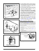
• When a 2-pipe system is used, the combustion air
intake and the vent exhaust must be located in the
same atmospheric pressure zone. This means both
pipes must exit the building through the same portion
of exterior wall or roof as shown in Figure 1, Figure 2
& Figure 4 (page 9) and Figure 29 (page 37).
• Piping must be mechanically supported so that its weight
does not bear on the furnace. Pipe supports must be
installed a minimum of every five feet along the vent run to
ensure no displacement after installation. Supports may
be at shorter intervals if necessary to ensure that there
are no sagging sections that can trap condensate. It is
recommended to install couplings (Figure 29) along the
vent pipe, on either side of the exterior wall. Couplings
may be required by local code.
• If breakable connections are required in the combustion
air inlet pipe (if present) and exhaust vent piping, then
straight neoprene couplings for 3” piping with hose
clamps can be used. These couplings can be ordered
through your local furnace distributor. To install a
coupling:
1. Slide the rubber coupling over the end of the pipe
that is attached to the furnace and secure it with one
of the hose clamps.
2. Slide the other end of the rubber coupling onto the
other pipe from the vent.
3. Secure the coupling with the second hose clamp,
ensuring that the connection is tight and leak free.
Outdoor Terminations - Horizontal Venting
• Vent and combustion air intake terminations shall be
installed as shown in Figure 1, Figure 2, Figure 3, &
Figure 4 and in accordance with these instructions:
• Vent termination clearances must be consistent with the
NFGC, ANSI 2223.1/NFPA 54 and/or the CSA B149.1,
Natural Gas and Propane Installation Code. Table 13,
(page 36) lists the necessary distances from the vent
termination to windows and building air intakes.
• Vent and combustion air intake terminations must
be located to ensure proper furnace operation and
conformance to applicable codes. A vent terminal
must be located at least 3 feet above any forced air
inlet located within 10 feet. This does not apply to the
combustion air inlet of a direct vent (two pipe) appliance.
In Canada, CSA B149.1 takes precedence over these
instructions. See Table 13.
• All minimum clearances (Figure 2) must be maintained
to protect building materials from degradation by flue
gases.
• For optimal performance, vent the furnace through a
wall that experiences the least exposure to winter winds.
Condensing furnace combustion products have very little
buoyancy, so Table 2 is to be used without consideration
of any vertical rise in the piping.
Vent Pipe Material
Vent and combustion air pipe and fittings must be one
of the following materials in the list and must conform to
the indicated ANSI/ASTM standards.
MATERIALS STANDARDS
SCHEDULE 40PVC ................................................... D1785
PVC-DWV .................................................................. D2665
SDR-21 & SDR-26 ..................................................... D2241
ABS-DWV .................................................................. D2661
SCHEDULE 40 ABS ....................................................F628
FOAM / CELLULAR CORE PVC .................................F891
*POLYPRO
®
BY DURAVENT ................................. ULC-S636
When joining PVC to PVC, use cement that conforms to
ASTM standard D2564. PVC primer must meet standard
ASTM F656. When joining ABS to ABS, use cement that
conforms to ASTM standard D2235. When joining PVC to
ABS, use cement as specified in procedure from ASTM
standard D3138.
In Canada, all plastic vent pipes and fittings including
any cement, cleaners, or primers must be certified as a
system to ULC S636. However this requirement does not
apply to the finish flanges or piping internal to the furnace.
Vent Pipe Installation
CAUTION:
Combustion air must not be drawn from a
corrosive atmosphere.
This furnace has been certified for installation with zero
clearance between vent piping and combustible surfaces.
However, it is good practice to allow space for convenience
in installation and service.
• In the absence of local codes, the location of any
combustion air inlet relative to any vent terminal must
be at least 8 inches. This includes installations involving
more than one furnace.