
StyleCrest Installation Manual

3
IMPORTANT SAFETY INFORMATION
INSTALLER: Please read all instructions before servicing
this equipment. Pay attention to all safety warnings and
any other special notes highlighted in the manual. Safety
markings are used frequently throughout this manual to
designate a degree or level of seriousness and should not
be ignored. WARNING indicates a potentially hazardous
situation that if not avoided, could result in personal injury
or death. CAUTION indicates a potentially hazardous
situation that if not avoided, may result in minor or moderate
injury or property damage.
REQUIREMENTS & CODES
WARNING:
This unit must be installed in accordance
with instructions outlined in this manual
during the installation, service, and operation
of this unit. Unqualified individuals should
not attempt to interpret these instructions or
install this equipment. Failure to follow safety
recommendations could result in possible
damage to the equipment, serious personal
injury or death.
• The installer must comply with all local codes and
regulations which govern the installation of this type
of equipment. Local codes and regulations take
precedence over any recommendations contained
in these instructions. Consult local building codes
and the National Electrical Code (NEC) for special
installation requirements.
• All electrical wiring must be completed in accordance
with local, state and national codes and regulations
and with the National Electric Code (ANSI/NFPA
70) or in Canada the Canadian Electric Code (CSA
Z240.6.1, & Z240.9.1).
• Design and construction of the home duct system,
must be in accordance with: HUD Manufactured Home
Construction & Safety Standard (Title 24, Part 3280)
and American National Standards (ANSI) A119.11,
C1-NFPA 7.
• Plenums and air ducts must be installed in accordance
with the Standard for the Installation of Air Conditioning
and Ventilating Systems (NFPA No. 90A) or the
Standard for the Installation of Warm Air Heating and
Air Conditioning Systems (NFPA No. 90B).
• Follow all precautions in the literature, on tags, and
on labels provided with the equipment. Read and
thoroughly understand the instructions provided with
the equipment prior to performing the installation and
operational checkout of the equipment.
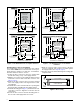
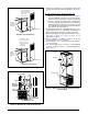
Minimum Installation Clearances
• Access for positioning and servicing the unit must be
considered when locating unit. The need to provide
clearance for access to panels or doors may require
clearance distances over and above the requirements.
For alcove installations allow 24 (61 cm) inches
minimum clearance from the front of the unit for
future servicing. Closet installations require 6
inches minimum.
• This appliance must be installed in accordance with
clearances listed in
Table 1. The furnace must be
installed with ample clearance for easy access to the
air filter, blower assembly, burner assembly, controls,
and vent connections.
• Locate and install this unit in position as specified
on page 5. This unit is designed only for Indoor
installations and should be located with consideration
of minimizing the length of the supply and return
ducts. See Table 4 (page 15), Table 5 (page 15), or
the rating plate for circulating airflow data.
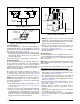
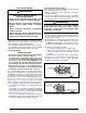
Minimum Unobstructed Airflow
• Sufficient clearance for unobstructed airflow must be
maintained in order to achieve rated performance. Air
return to the furnace must have the minimum required
total free area:
— 200 in
2
(1290 cm
2
) for furnace only. May also
include return air grille and frame assembly P/N
902989 or wall mount grille P/N 902999).
— 235 in
2
(1516 cm
2
) with 4 ton or smaller A.C. or
H.P. installed.
— 250 in
2
. (1613 cm
2
) with 4 ton or smaller A.C. or
H.P. installed & 1” special clearance.
— 275 in
2
(1775 cm
2
) with up to 5 ton A.C. or H.P.
installed.
• If using louvered doors, the total free area must be
calculated. Louvered doors installed at the factory are
about 70% free area. If using a third party louvered
door manufacturer, check their technical specifications
to determine the free area.
• For closet installations with less than 6” front clearance,
but not less than 1”, a louvered door must be used
having a minimum 250 sq in2 (1,613 cm2) free area
opening directly in line with openings in the furnace
door
Clearances to Combustible Materials
• This furnace is Design Certified in the U.S. and Canada
by ETL for the minimum clearances to combustible
materials. NOTE: The furnace is listed for installation
on combustible or non-combustible flooring. To obtain
specific clearance information, refer to the furnace
rating plate, located inside of the furnace cabinet.
• 0” from all surfaces of furnace cabinet, ducts, optional
coil housing and plenum connector. No separate
subbase required for installations on combustible
flooring.
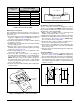
Table 1. Minimum Clearance Requirements
ALL MODELS CLOSET ALCOVE
Front ** 6" 24"
Back 0" 0"
Sides* 0" 0"
Top 0" 0"
Top & Sides of Duct 0" 0"
Bottom of Duct 0" 0"
*For upflow application using upflow stand, 3” minimum per side.
**Service Clearance