
StyleCrest Installation Manual

5
• Install a filter with a minimum unrestricted medium
area that meets the application requirements of the
furnace below the coil cabinet/furnace assembly that
is accessible for monthly cleaning or replacement by
the homeowner
Optional Equipment
NOTE: Refer to the instructions supplied with any additional
accessories for further installation details.
Optional Automatic Furnace Damper
Furnace may be equipped with the optional automatic
damper when a packaged air conditioner is installed and
connected to the warm air duct system. This damper (not
required) prevents cooled air from discharging through
the furnace cabinet, causing excessive cooling of the
immediate area. Refer to the instructions supplied with
the damper for details.
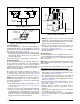
Duct Connectors for Downflow Systems
Duct connectors are recommended for heated air
distribution in under-the-floor duct systems. With this
system, furnaces may be installed on combustible flooring
without a separate sub-base. The furnace rear mounting
plate (Figure 5 (page 7)) supplied with the duct connectors
is recommended for use with this type of installation.
FURNACE INSTALLATION
NOTE: Since all installations are different, the sequence of
these steps may differ from the actual installation. These
installation procedures are suggested for typical furnace
installations. Only qualified HVAC technicians should
install this furnace.
General Information
This electric furnace is designed only for indoor
installations. Units are approved for single/multistory
residential or mobile / modular / manufactured structures
in upflow and downflow (freestanding / closet / alcove)
configurations.
Approved installation, operation, and maintenance of
this appliance must be in accordance with the listed
specifications contained in these instructions and other
documents supplied with the furnace and/or optional air
conditioning equipment. Unless it is noted differently in this
manual, only use factory authorized kits and accessories
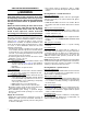
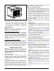
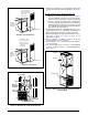
24 3/4” (628 mm)
Upflow Stand
20”
(508 mm)
20” (508 mm)
Figure 1. Optional Upflow Stand
when modifying this appliance. Refer to local authorities
having jurisdiction for further information.
Before You Install this Furnace
√ This equipment is securely packaged at the time of
shipment and upon arrival should be carefully inspected
for damage prior to installing the equipment at the
job site. Claims for damage (apparent or concealed)
should be filed immediately with the carrier.
√ Check the electrical supply and verify the power
supply is adequate for unit operation. The system
must be wired and provided with circuit protection in
accordance with local building codes. If there is any
question concerning the power supply, contact the
local power company.
√ Verify the air delivery of the furnace is adequate to
handle the static pressure drop of the coil, filter, and
duct work.
Locating the Unit
• Survey the job site to determine the best location
for installing the unit. Consideration should be given
to availability of electric power, service access, and
noise.
• The dimensions of the room or alcove must be able
to accommodate the overall size of the unit and the
installation clearances in
Table 1 (page 3). Physical
dimensions for this furnace are shown in Figure 17
(page 13)
. If an upflow stand will be used, see Figure
19 (page 14)
for component dimensions.
• The unit must be leveled at installation and attached to
a properly installed duct system.
• The surface that the furnace is mounted on must
provide sound physical support of the unit.
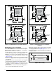
Locating & Cutting Floor Openings
Floor cut-outs must be carefully located to avoid
misalignment of the furnace and air duct. Standard and
round cutouts for upflow furnaces are shown in Figure 2
(page 6)
. The cutouts for downflow furnaces are shown
in Figure 3 (page 6).
1. Measure and mark the centerline of the cutout. Provide
minimum clearances at rear and right side walls of closet
or alcove for installation of furnace and wiring.
2. Using the centerline as a starting point, draw the rest
of the duct cut-out to the dimensions shown in Figure 2
or Figure 3.
NOTE: Additional provisions may be necessary for
optional air conditioning or heat pump if refrigerant
lines are installed elsewhere than at the front of the
furnace. The refrigerant and entrance supply opening
dimensions may be adjusted ± 1/2”.
3. Cut out the floor opening 1/16” larger than the actual
cutout drawn. This will allow some clearance when
installing the duct connector.
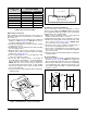
4. Measure from the top of the floor down to the top of the
supply air duct to obtain the depth of the floor cavity.
NOTE: The depth of the floor cavity (shown as “X”)
in Figure 4 (page 6) will determine the correct duct
connector.
5. Determine which duct connector to use from Table 2
(page 7)
.