
StyleCrest Installation Manual

6
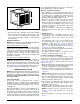
“X”
FLOOR OPENING
FLOOR
CAVITY
SUPPLY AIR DUCT
Figure 4. Floor Cavity
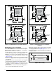
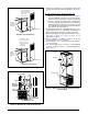
Figure 2. Cut-Out Dimensions for Upflow Furnaces
FLOOR CUT-OUT
17 1/2” X 14”
FOR UPFLOW
FURNACES WITH
STD. DUCT
CONNECTORS
23 3/4"
OPTIONAL
REFRIGERANT LIN
E
3 1/8” X 5 3/4”
REAR WALL OF CLOSET OR ALCOVE
3/4"
FURNACE OUTLINE
FURNAC
E
DOOR
3”
C
L
20"
10"
18 5/8"
1 3/4" MIN.
23 3/4"
OPTIONAL
REFRIGERANT LIN
E
3 1/8” X 5 3/4”
REAR WALL OF CLOSET OR ALCOVE
3/4"
FURNACE OUTLINE
FURNAC
E
DOOR
3”
20"
10"
18 5/8"
1 3/4"
MIN.
FLOOR CUT-OUT
14 1/4” DIAMETER
FOR UPFLOW
FURNACES WITH
ROUND DUCT
CONNECTORS
C
L
STANDARD DUCT CONNECTOR
ROUND DUCT CONNECTOR
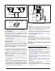
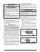
Standard Duct Connector Installation
The standard duct connector is designed for use on ducts
12” in width. NOTE: Ducts narrower than 12” may not
allow sufficient clearances for this type of installation.
See Narrow Duct Connector section.
1. Center the duct connector in the floor opening with
bottom tabs resting on top of the supply air duct.
2. Mark the cut-out area on the supply air duct by tracing
around the connector tabs of the duct connector. See
Figure 5 (page 7).
3. Remove the duct connector and cut out the marked
area of the supply air duct 1/4” larger than the actual
cutout drawn.
4. Install the duct connector back in the floor opening with
the bottom tabs extending into the supply air duct.
5. Install the mounting plate (Figure 5) under the back side
of the duct connector. Align the screw holes in both
components.
6. Secure the duct connector and the mounting plate to
the wood floor with appropriate size screws.
7. Bend the connector tabs on the bottom of the duct
connector upwards and as tight as possible against
the supply air duct. See
Figure 6 (page 7).
8. Seal all connections with industrial grade sealing tape
or liquid sealant.
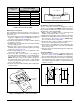
Figure 3. Cut-Out Dimensions for Downflow
Furnaces
FLOOR CUT-OUT
14 1/2” X 14 1/2”
FOR DOWNFLOW
FURNACES WITH
STD. DUCT
CONNECTORS
23 3/4"
17"
2 3/8" MIN.
OPTIONAL
REFRIGERANT LIN
E
4 1/4” X 3 3/4”
REAR WALL OF CLOSET OR ALCOVE
3/4"
FURNACE OUTLINE
FURNACE
DOOR
5”
C
L
OPTIONAL SUPPL
Y
WIRE ENTRANCE
3” X 6 1/4”
20"
3 3/8”
16 5/8"
10"
23 3/4"
17"
2 3/8"
MIN.
OPTIONAL
REFRIGERANT LIN
E
4 1/4” X 3 3/4”
REAR WALL OF CLOSET OR ALCOVE
3/4"
FURNACE OUTLINE
FURNACE
DOOR
5”
OPTIONAL SUPPL
Y
WIRE ENTRANCE
3” X 6 1/4”
20"
3 3/8”
16 5/8"
10"
FLOOR CUT-OUT
14 1/4” DIAMETER
FOR DOWNFLOW
FURNACES WITH
ROUND DUCT
CONNECTORS
C
L
STANDARD DUCT CONNECTOR
ROUND DUCT CONNECTOR