
StyleCrest Installation Manual

7
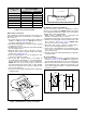
IF FLOOR CAVITY
“X” IS:
DUCT CONNECTOR
TYPE & PART NUMBER
STANDARD DUCT SCREW DOWN
7/8” / (22) 901987A 904008
2” / (51) 901988A 904009
4-1/4” / (108) 901989A 904010
6-1/4” / (159) 901990A 904011
8-1/4” / (210) 901991A 904012
10-1/4” / (260) 901992A 904013
12-1/4” / (311) 901993A 904014
NOTE: Dimensions shown as Inches / (Millimeter)
Table 2. Duct Connector Sizes
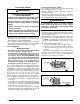
Narrow Duct Connectors
This attachment method should be used if there is
insufficient clearance to bend the tabs on a standard 12”
duct connector.
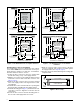
1. Score and cut the top of the supply air duct as indicated
in Option 1 or Option 2 (
Figure 7). With Option 1 choice,
cut out the metal from the shaded area.
2. Fold the two flaps (Options 1 or 2) up to form the opening
for the duct connector.
3. Install the duct connector with the bottom tabs extending
into the supply air duct.
4. Bend the tabs on the bottom of the duct connector
upwards and as tight as possible against the supply
air duct. See Figure 8 (page 8).
5. Form the flaps (Options 1 or 2) up against the duct
connector as tight as possible.
6. Secure the duct connector flaps to the supply air
duct with staples (3 minimum) or if a 2x block/joist is
not provided, use sheet metal screws (2 minimum).
NOTE: The duct connector tabs may be attached to
the air duct with sheet metal screws or other suitable
fasteners as long as the duct connector and the air duct
are securely attached.
7. Seal all connections with industrial grade sealing tape
or liquid sealant.
Figure 7. Narrow Air Duct Openings
OPTION 1 OPTION 2
SUPPLY
AIR DUCT
FOLD FLAP HERE
FOLD FLAP HERE
REMOVE
THIS
FLAP
REMOVE
THIS
FLAP
CUT HERE
CUT HERE
CUT HERE
CUT HERE
CUT HERE
CUT HERE
CUT HERE
CUT HERE
CUT HERE
FOLD FLAP HERE
FOLD FLAP HERE
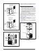
Figure 6. Duct Connector Tabs
DUCT CONNECTOR
SUPPLY
AIR DUCT
BEND TABS TIGHTLY
AGAINST SUPPLY AIR DUCT
MOUNTING
PLATE
DUCT
CONNECT
OR
CONNECTOR
TABS
SUPPLY
AIR DUCT
WOOD FLOOR
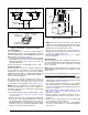
Figure 5. Standard Duct Connector Installed
Round Duct Connector Installation
The 14” round duct connector is designed to connect
directly to a 14” flexible duct. NOTE: Flexible ducts must
have a minimum temperature rating of 200° F and meet
all applicable codes and standards.
1. Apply a bead of caulking, mastic, or other approved
sealant around bottom side of connector.
2. Install and center the duct connector in the floor opening.
3. Install the mounting plate under the back side of the
duct connector. See Figure 9 (page 8). NOTE: Align
the screw holes in both components.
4. Secure the duct connector and the mounting plate to
the wood floor with appropriate size screws.
5. Connect the round supply duct to the underside of the
duct connector and secure them with field supplied
sheet metal screws.
6. Seal all connections with industrial grade sealing tape
or liquid sealant.
Alcove Installation
1. Cut alcove rough openings to minimum dimensions
shown in Figure 10 (page 8). NOTE: The height may
increase depending on the size of the coil compartment.
2. Attach a return air method to the furnace. Depending
on the application, this could be a louvered door coil
box, frame and grille assembly, or an upflow stand with
solid door coil box.