
StyleCrest Installation Manual

9
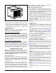
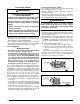
7. Install return air grille in closet preferably at same level
as upflow stand or below mounting platform. See Figure
12
.
Through-the-Floor Return Air System (Ducted)
1. Prepare Floor Opening(s):
a. Mark floor openings as shown in Figure 2 (page 6).
Provide minimum clearances at rear and left side
walls of closet for installation of furnace and wiring.
b. Cut floor opening on outside edge of marked line
so that opening is slightly larger than area marked.
c. Additional provisions may be necessary for optional
air conditioning if refrigerant lines are installed other
than at the front of the furnace.
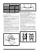
2. If return air duct is made of combustible material, locate
a pan fabricated of non-combustible material with 1”
upturned flanges under furnace return air opening.
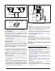
3. Route 240V supply circuit(s) and 24V wiring to closet.
See Figure 17 (page 13) or Figure 18 (page 13) for
appropriate locations.
4. Position optional coil cabinet over floor cutout and
secure with three or more fasteners.
5. Position furnace onto coil cabinet and secure with two
or more fasteners.
6. Use optional upflow duct connector or field supplied
connector to attach furnace to overhead supply duct.
See Figure 13.
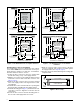
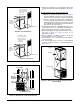
Figure 12. Over-the-Floor Return Air System
Coil Cabinet
Air Filter
Braced
Mounting
Platform
Front
Grille
Non-combustible
Pan or
Enclosure
WALL
FLOOR
0" Side
Clearance
to Furnace
Cabinet
Provide min. 235
sq. in. (1516 cm )
open free area in
front or side wall
or in top of
closet door
CLOSET DOOR
6"
(152 mm)
0" Side
Clearance
to Furnace
Cabinet
Provide min. 250
sq. in. (1613 cm
2
)
open free area in
front or side wall
or in top of
closet door
CLOSET DOOR
1"
(25 mm)
Standard Closet Installation
Special 1" Clearance
Figure 11. Closet Installation
Figure 13. Over-the-Floor Return Air System with
Upflow Stand
Upflow Duct
Connector
Furnace
Upflow Stand