ITEM #0667535 ELECTRIC FIREPLACE WITH MEDIA MANTEL Style Selections® is a registered trademark of LF, LLC. All rights reserved. MODEL #88287/26MM8715-Z248 Français p. 21 Español p. 41 Questions, problems, missing parts? Before returning to your retailer, call our customer service department at 1-877-888-8225, 8 a.m. - 8 p.m., EST, Monday - Friday. EB15208 1 Lowes.
TABLE OF CONTENTS Product Specifications .......................................................................................................................... 2 Safety Information................................................................................................................................. 3 Package Contents................................................................................................................................. 6 Hardware Contents...............................
SAFETY INFORMATION Please read and understand this entire manual before attempting to assemble, operate or install the product. When using electrical appliances, basic precautions should always be followed to reduce the risk of fire, electrical shock and injury to persons, including the following: DANGER: • This heater is not intended for use in bathrooms, laundry areas and similar indoor locations. Never place this appliance where it may fall into a bathtub or other water container.
. The appliance is not to be used by children or persons with reduced physical, sensory or mental capabilities, or lack of experience and knowledge, unless they have been given supervision or instruction. SAFETY INFORMATION 5. Always unplug this appliance when not in use. 6. Do not operate any heater with a damaged cord or plug or after the appliance malfunctions, or if it has been dropped or damaged in any manner. • 7.
SAFETY INFORMATION • Batteries are to be inserted with the correct polarity. • Exhausted batteries are to be removed from the product. • Non-rechargeable batteries are not to be recharged. SAVE THESE INSTRUCTIONS. Cold-climate installation: It is mandatory the outer walls be insulated to conform to applicable insulation codes. ELECTRICAL CONNECTION A 15-Amp, 120-volt, 60 Hz circuit with a properly grounded outlet is required.
PACKAGE CONTENTS G I C P H Q K O R T U V W H S D I H M N F H B J L E PART A B C D E F G H I J K L M N O P Q R S T U V W X Y X A DESCRIPTION Front Base Left Side Panel Right Side Panel Center Front Panel Left Door Right Door Mantel Top Wood Shelf Upper Side Panel Center Left Side Panel Center Right Side Panel Left Base Right Base Lower Insert Support Bar Center Shelf Support Panel Center Upper Back Panel Side Back Panel Insert Support Bar Tipping Restraint Hardware Pack 2-Block Conne
HARDWARE CONTENTS (shown actual size) AA BB Wood Dowel Qty: 10 Truss Head Screw Qty: 30 CC DD Shelf Pin Qty: 16 EE Door Pull (Not to scale) Screw Qty: 8 Qty: 2 FF GG HH Long Screw Qty: 6 Bolt Qty: 56 Long Bolt Washer Door Bumper Qty: 6 Qty: 6 Qty: 4 II JJ KK W3348A Touch-up Pen (Not to scale) Qty: 1 7 Lowes.
PREPARATION Before beginning assembly of product, make sure all parts are present. Compare parts with package contents list and hardware contents list. If any part is missing or damaged, do not attempt to assemble, install or operate the product. To protect the product from possible scratches, please assemble the parts on a scratch-free surface. Estimated Assembly Time: 60 minutes Tools Required for Assembly (not included): Phillips screwdriver, scissors and utility knife.
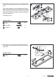
3. Insert plastic blocks from 3-block connector pack (V) into lower insert support bar (N), securing with bolts (GG). 3 II HH Then, align left base (L) and right base (M) to front base (A), and slide lower insert support bar (N) where shown, securing with bolts (GG). Secure left base (L) and right base (M) to front base (A) using long bolts (HH) and washers (II). M A N Set aside for later. L V Hardware Used GG GG Bolt x6 HH Long Bolt x6 Washer x6 II 4.
5. Attach support panel (P) where shown to mantel top (G) using bolt (GG). 5 GG U P Hardware Used GG Bolt x1 G 6. Insert wood dowels (AA) into assembly where shown, then attach center shelf (O). Secure from underneath using bolts (GG) and from above using long screws (FF). 6 FF AA Hardware Used O AA Wood Dowel x2 FF Long Screw x2 GG Bolt x4 GG 7. Attach left side panel (B) and right side panel (C) to center shelf (O) using bolts (GG).
8. Insert plastic blocks from 2-block connector pack (U) where shown into center front panel (D). Secure with bolts (GG). 8 BB Insert wood dowels (AA) into each end of center front panel (D), then attach center front panel (D) to center left side panel (J) and center right side panel (K). Slide preassembled connection plates on center front panel (D) to align with corresponding holes on center left side panel (J) and center right side panel (K). Secure using truss head screws (BB).
10. Insert wood dowels where shown into assembly, then attach base assembly from Step 3 to unit. Secure where shown with long screws (FF). 10 FF Hardware Used GG AA Wood Dowel x4 FF Long Screw x4 GG Bolt x4 AA 11. Set the assembly upright. Attach the center upper back panel (Q) and rear panels (R) to the back of the assembly using truss head screws (BB). 11 Q Hardware Used BB Truss Head Screw x 28 BB R BB 12.
. Remove the preassembled bolts from the door pulls (DD), then install door pulls (DD) to left door (E) and right door (F) with the bolts. 13 E F Hardware Used DD Door Pull x2 DD 14. Attach left door (E) and right door (F) to assembly using screws preassembled to the hinges. 14 To adjust the doors forward or backward, change keyhole slot position as in (a). To adjust the doors right or left, loosen/tighten screw (b).
16. Align insert support bar (S) with the holes on center right side panel (K) and center left side panel (J). Attach plastic blocks from 2-block connector pack (U) where shown to secure insert support bar (S). Secure with bolts (GG). 16 J S Hardware Used GG Bolt x4 U GG K 17. Choose desired height of wood shelf (H) and place four shelf pins (CC) into the corresponding holes. Insert wood shelf (H) on top of the shelf pins (CC). Repeat as desired for the other wood shelves (H).
19. WARNING: Installing the tipping restraint hardware will help prevent accidents and/or damage to the unit. It is highly recommended you complete this step. To secure the item to the wall, find and mark a stud closest to the edge of the left side of the mantel. Attach the wall anchor from the tipping restraint hardware pack (T) at the marked locations using 2 of the screws from the pack. Attach the unit anchor to the mantel top (G) using the remaining 2 screws so it aligns with the wall anchor.
OPERATING INSTRUCTIONS The heater can be operated by either the remote control or the control panel. Control Panel Display Front View of Insert (Y) FUNCTION POWER ICON Remote (X) DESCRIPTION Use the POWER button to turn on or off the fireplace from the remote or control panel. Note: Holding the POWER button on the control panel for 10 seconds will disable the heater function. To re-enable the heater, press and hold the POWER button for another 10 seconds.
CARE AND MAINTENANCE • Dust the fireplace regularly with a soft, non-lint producing cloth or household dusting product. • Clean the fireplace with a gentle non-abrasive household cleaner. Make sure to dry the fireplace immediately with a soft cloth or towel. • Tips for using touch-up pen (KK): For scratches, stroke in direction of scratch. For worn areas, stroke in direction of wood grain. Rub excess colorant promptly with a soft cloth.
TROUBLESHOOTING PROBLEM POSSIBLE CAUSE CORRECTIVE ACTION Display shows “ ”. The thermostat sensor is broken or disconnected. Unplug the fireplace, remove the back panel of the fireplace and check that the thermostat is plugged into the main circuit board. If this does not solve the problem, contact customer service for a replacement thermostat sensor. Display shows “ ”. The thermostat sensor is broken. Contact customer service for a replacement thermostat sensor.
1-YEAR LIMITED WARRANTY The manufacturer warrants this product to be free from manufacturing and material defects for a period of one year from date of purchase, subject to the following conditions and limitations. 1. Install and operate this item in accordance with the installation and operating instructions furnished with the product at all times. Any unauthorized repair, alteration, willful abuse, accident or misuse of the product shall nullify this warranty. 2.
REPLACEMENT PARTS LIST For replacement parts, call our customer service department at 1-877-888-8225, 8 a.m. - 8 p.m., EST, Monday - Friday. PART DESCRIPTION PART NO.