
Use and Care Manual

13
HomeDepot.com
Please contact 1-877-527-0313 for further assistance.
14
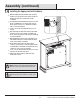
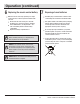
When the Tipping Restraint Hardware (FF) is properly
installed, it can provide protection against unexpected
tipping of the Unit due to small tremors, bumps
or climbing.
Each Tipping Restraint Hardware (FF) includes one Unit
Anchor, one Wall Anchor, one Anchor Tether, and four
Anchor Screws. Use these to complete the following
steps for a proper installation.
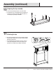
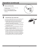
Locate a secure wall stud behind the unit closest to
left side.
Align the Unit Anchor with a wall stud and attach with
two Anchor Screws using a Philips Screwdriver. The
Anchor Screws must pass through the Top Assembly (G)
for proper installation.
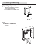
Align the Wall Anchor in the center of the wall stud, at
level with the Unit Anchor, and attach with two Anchor
Screws using a Philips Screwdriver.
On the Anchor Tether, detach the cable from the
connector and loop the loose cable through the eyelets
on the Wall Anchor and Unit Anchor. Reattach the loose
cable to the connector, but do not tighten.
Locate a secure wall stud behind the unit closest to the
right side, and repeat the steps above.
Tighten both Anchor Tethers by pulling the cable
the through connector.
Installing the tipping restraint hardware
WARNING:
Installing the Tipping Restraint
Hardware will help prevent accidents or damage to the
unit.
NOTE:
Installation of the Tipping Restraint Hardware (FF)
will provide a small space between the wall and the unit.
Assembly (continued)
G
FF