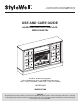
007529263/319988486/611768150779/23MMP35163-PT85 1007529317/319988377/611768148875/23MMP35163-PO140 USE AND CARE GUIDE HAZELTINE ELECTRIC FIREPLACE MEDIA MANTEL Questions, problems, missing parts? Before returning to the store, call StyleWell Customer Service 8 a.m. - 7 p.m., EST, Monday - Friday, 9 a.m. - 6 p.m., EST, Saturday 1-877-527-0313 HOMEDEPOT.COM THANK YOU We appreciate the trust and confidence you have placed in StyleWell through the purchase of this electric fireplace.
Table of Contents Maximum Load Warning............................................ 2 Safety Information...................................................... 3 Warranty...................................................................... 5 Pre-Assembly.............................................................. 6 Hardware Included ................................................... 6 Product Specifications........................................................ 6 Tools Required.........................
Safety Information Please read and understand this entire manual before attempting to assemble, operate or install the product. If you have any questions regarding the product, please call customer service at 1-877-527-0313, 8 a.m.-7 p.m., EST, Monday-Friday, 9 a.m. - 6 p.m., EST, Saturday. When using electrical appliances, basic precautions should always be followed to reduce the risk of fire, electrical shock, and injury to persons including the following: 1. 2. 3. 4. 5. 6. 7. 8.
Safety Information (continued) NOTE: Use care in assembling your new fireplace. Take your time and use the hardware provided and a quality Phillips head screwdriver. Never overtighten bolts. Do not sit on any part of the mantel. It is recommended to work on a soft surface like a rug or to lay out a blanket to protect the furniture from getting scratched during the assembly process.
Warranty Warranty 1 Year Limited Warranty: The manufacturer warrants that your new electric fireplace is free from manufacturing and material defects for a period of one year from date of purchase, subject to the following conditions and limitations. 1. Install and operate this appliance in accordance with the installation and operating instructions furnished with the product at all times. Any unauthorized repair, alteration, willful abuse, accident, or misuse of the product shall nullify this warranty.
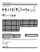
Pre-Assembly HARDWARE INCLUDED AA BB OO PP Part CC QQ DD EE RR Description FF GG HH II JJ KK LL Part Number Quantity Description Part Number MM Shelf Pin PH-SPNPCSPLB2 8 NN Handle (with Screw) VNA0851 2 OO Threaded Insert (Pre-attached) PH-THRZNC001 4 7 PP Floor glide (Pre-attached) PH-GLDBRW001 6 4 QQ Metal Plate (Pre-attached) PH-PLTBRZ001 4 PH-23MMP35163-BH 2 SET PH-23MMWIRECLIP 3 AA PH-BLTBLK002 4 BB Tipping Restraint Hardware PH-FTRHH510 1 CC Scr
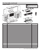
Pre-Assembly (continued) PACKAGE CONTENTS NOTE: All panels are labeled left and right as viewed from the front of unit.
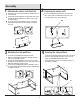
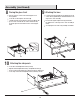
Assembly 1 Attaching the center shelf front rail 2 Preparing the center shelf Align the top of Center Shelf Front Rail (O) with the bottom of Center Shelf (B). Insert the pre-installed hardware on the bottom of the Center Shelf (B) into the pre-drilled holes on the top of the Center Shelf Front Rail (O). Secure the Center Shelf Front Rail (O) to the Center Shelf (B) by tightening the fasteners with a Phillips screwdriver as shown.
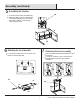
Assembly (continued) 5 Assembling the fireplace DD Locate the Front Panel with Control Button (EA). Using Screws (DD), secure the Front Panel with Control Button (EA) between the Left and Right Side Partitions (D and E) and just below the Center Shelf (B) as shown. D B E EA 6 Attaching the insert brackets Locate the Brackets (EF) and secure to each side of the Heater Box (EB) using Bolts (EE).
Assembly (continued) 8 Placing the glass front Turn the unit over so that Control Panel Support is now facing upward. Locate the electric fireplace Glass Panel (N). Carefully insert the electric fireplace Glass Panel (N) into the grooves of the surround rails as shown. Slide all the way in until the glass meets the bottom of the Control Support Panel.
Assembly (continued) 11 Installing the USB port GG Slide the USB Output (HH) through the opening in the Center Shelf (B). Carefully secure the USB output (HH) in place using Screws (GG) and a Phillips screwdriver. 12 Attaching the back panels Locate the Back Side Panels (I) and Middle Back Panel (J). Slide the Back Side Panels (I) into the grooves between the inner and outer side panels as shown. Slide all the way down until the Back Side Panels (I) meet the bottom shelf.
Assembly (continued) 14 Attaching the top panel Place the Top Panel (G) on top of the main assembly while aligning the pre-installed screws on the edges of the main assembly with the pre-drilled screw holes on the Top Panel (G). After inserting the screws (BB) into the holes, tighten the fasteners from underneath the Top Panel (G) using a Phillips screwdriver as shown.
Assembly (continued) 17 Attaching the cabinet doors Lift the Left Door (K) and align the hinges with the pre-attached hardware on the main assembly as shown. Slide the barrel of the hinge on the door downward onto the pin of the hardware on the main assembly. Repeat steps with the Right Door (L). L K 18 Inserting the adjustable shelves Locate the two Adjustable Shelves (M). Insert the Shelf Pins (MM) into the pre-drilled holes on the inside of each cabinet side panel at your desired height.
Assembly (continued) 20 Assembling the log set Route the wires of the Log Set Left (EC) and the Log Set Right (ED) down the back of the Ember Bed (EG) and into the receiving tabs to secure in place. Refer to the lower diagram. Gently plug the cords from both the Log Set Left (EC) and the Log Set Right (ED) into the ports as shown. Ensure the cords are plugged in straight.
Assembly (continued) 23 Connecting the fireplace wiring 24 Placing the fireplace background Locate the Back Panel (C). Only slightly bend the wallpaper and fit it into the back of the fireplace. Connect Key Button Connection Wire to heater. Insert the Ember Bed Connection Wire into the heater. Route the Ember Bed Connection Wire down the side surround rail and along the back of the log set, securing it in place with the clips as shown.
Assembly (continued) 26 Installing the tipping restraint hardware BB When the Tipping Restraint Hardware (BB) is properly installed, it can provide protection against unexpected tipping of the unit due to small tremors, bumps or climbing. Each Tipping Restraint Hardware (BB) includes one Unit Anchor, one Wall Anchor, one Anchor Tether, and two Anchor Screws. Use these to complete the following steps for a proper installation. Wall Locate a secure wall stud behind the unit closest to the left side.
Operation Operation NOTE: The control panel can be accessed at the upper-right corner of the insert. 1 Powering the fireplace 2 Push the Power button to supply power to all functions of the fireplace and put the insert in a standby mode. Push the Power button again to turn off all functions. Adjusting the flame There are 5 brightness levels that can be selected and OFF (00) setting. Settings F5 - F1 decrease in brightness.
Operation (continued) 6 Replacing the remote control battery 7 Disposing of used batteries The battery may contain hazardous substances that could endanger the environment and human health. When the remote control stops operating or its range seems reduced, it is time to replace the batteries with new ones. On the back end of the remote, press and slide the battery door open and remove the old battery.
Operation (continued) 8 Power cord information This heater is for use on 120 volts. The cord has a plug as shown in the figure. Connect to properly grounded outlets only. Do not use a two-prong adapter. Never use with an extension cord or relocatable power tap (outlet/ power strip). 9 Patented Safer Plug® information This product is equipped with a Safer Plug®, which is an advanced safety device that helps prevent electrical fires caused from faulty outlets.
FCC/IC Information WARNING: Changes or modifications to this unit not expressly approved by the party responsible for compliance could void user’s authority to operate the equipment. NOTE: This equipment has been tested and found to comply with the limits for Class B digital device, pursuant to part 15 of the FCC Rules. These limits are designed to provide reasonable protection against harmful interference in a residential installation.
Troubleshooting PROBLEM ROOT CAUSE CORRECTIVE ACTION Fireplace has reached set temperature. Fireplace stopped heating before reaching Temperature around fireplace might be a few the desired temperature. degrees higher than other area in the room. Set the fireplace to a higher temperature or always “on”. Display shows " " The thermostat sensor is broken or disconnected. Unplug the fireplace, remove the back panel of the fireplace and check that the thermostat is plugged into the main circuit board.
Troubleshooting PROBLEM The remote control is not working. ROOT CAUSE CORRECTIVE ACTION There are no batteries. Change the remote batteries. The signal is poor. Operate remote transmitter at a slow measured pace. Press the remote control buttons with an even motion and gentle pressure. Repeatedly pressing buttons in rapid succession may cause the transmitter to malfunction. The remote is too far from the heater.
Replacement Parts For replacement parts, call our customer service department at 1-877-527-0313, 8 a.m.-7 p.m., EST, Monday-Friday, 9 a.m. - 6 p.m., EST, Saturday. Part Description Qty.
Notes 24
Notes 25 HomeDepot.com Please contact 1-877-527-0313 for further assistance.
Notes 26
Notes 27 HomeDepot.com Please contact 1-877-527-0313 for further assistance.
Questions, problems, missing parts? Before returning to the store, call StyleWell Customer Service 8 a.m. - 7 p.m., EST, Monday - Friday, 9 a.m. - 6 p.m., EST, Saturday 1-877-527-0313 HOMEDEPOT.COM Retain this manual for future use.