B U I LT - I N R E F R I G E R AT I O N I NSTALLATION I NSTRUCTIONS
CONTENTS Installation Recommendations 3 Installation Specifications 4 Installation Instructions 8 Framed Panel Installation 12 Overlay Panel Installation 16 Completing the Installation 20 Service Information 23 Specifications are subject to change without notice. Check our website, subzero.com, for the most up-to-date specifications. As you follow these instructions, you will notice WARNING and CAUTION symbols.
B U I LT- I N I N S TA L L A T I O N R E C O M M E N D A T I O N S I N S TA L L AT I O N R E C O M M E N D AT I O N S The importance of the installation of the Sub-Zero Built-In unit cannot be overemphasized. Installation should be done by a qualified installer. Before you begin the installation process, it is recommended that you read this entire Installation Instructions book. There are key details that you should take special care to observe during the installation.
B U I LT- I N I N S TA L L A T I O N S P E C I F I C A T I O N S I N S TA L L AT I O N S P E C I F I C AT I O N S Make sure that the actual equipment that was shipped to you matches the design you are expecting to install. The Sub-Zero Built-In line offers the following design alternatives— framed, overlay and stainless steel models. Each of these design options has specific installation requirements, which means it is vital that the unit match your planning and space needs.
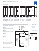
B U I LT- I N I N S TA L L A T I O N S P E C I F I C A T I O N S OVERALL DIMENSIONS All Refrigerator | All Freezer Models 73" 73" 73" (1854) (1854) (1854) A L L R E F R I G E R AT O R ALL FREEZER Model 601R All Refrigerator Model 601RG All Refrigerator with Glass Door 36" 36" 36" 24" (914) (914) (914) (610) Model 601R Model 601RG Model 601F All Refrigerator All Refrigerator with Glass Door All Freezer Width Width Width 36" (914) 36" (914) 36" (914) Height 73" (1854) Height 73"
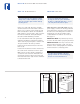
B U I LT- I N I N S TA L L A T I O N S P E C I F I C A T I O N S OVERALL DIMENSIONS Over-and-Under Models OVER-ANDUNDER 84" 84" 84" 84" (2134) (2134) (2134) (2134) Model 611 Model 611G with Glass Door Model 650 Model 650G with Glass Door 30" 30" 36" 36" 24" (762) (762) (914) (914) (610) Model 611 Model 611G Model 650 with Glass Door Width 30" (762) Width 30" (762) Model 650G with Glass Door Width 36" (914) Width 36" (914) Height 84" (2138) Height 84" (2138) Height 84" (2
B U I LT- I N I N S TA L L A T I O N S P E C I F I C A T I O N S OVERALL DIMENSIONS Side-by-Side Models 84" (2134) 36" 42" 42" 48" 48" 24" (914) (1067) (1067) (1219) (1219) (610) Model 661 Model 642 Model 685 Model 632 Model 695 Ice | Water Dispensing Width 36" (914) Width 42" (1067) Width Ice | Water Dispensing 42" (1067) Width 48" (1219) Width 48" (1219) Height 84" (2138) Height 84" (2138) Height 84" (2138) Height 84" (2138) Height 84" (2138) Depth Depth Depth Depth
B U I LT- I N I N S TA L L A T I O N I N S T R U C T I O N S ELECTRICAL R E Q U I R E M E N T S PLUMBING R E Q U I R E M E N T S A 115 V AC, 60 Hz, 15 amp circuit breaker and electrical supply are required. A separate circuit, servicing only this appliance, is required. For Built-In models with an automatic ice maker, rough in the water supply line. Connect a 1/4" OD copper line to the house supply. Use an easily accessible shut-off valve between the water supply and the unit.
B U I LT- I N I N S TA L L A T I O N I N S T R U C T I O N S U N PAC K T H E U N I T GRILLE R E M O VA L Uncrate the unit, remove its wood base and discard the shipping bolts that hold the wood base to the bottom of the unit. Remove all packing materials and tape. In order to prevent damage to the grille and to access the power cord, the top grille assembly should be removed prior to moving the unit. IMPORTANT NOTE: Do not discard the kickplate, anti-tip blocking kit and hardware.
B U I LT- I N I N S TA L L A T I O N I N S T R U C T I O N S ANTI-TIP B L O C K I N G K I T POSITION T H E U N I T To prevent the unit from tipping forward and provide a stable installation, the unit must be secured in place with an anti-tip blocking device. Protect any finished flooring before moving the unit into place. All Built-In models are equipped with rollers, so you can easily move the unit into place.
B U I LT- I N I N S TA L L A T I O N I N S T R U C T I O N S WAT E R L I N E C O N N E C T I O N LEVEL T H E U N I T To connect the ice maker water line, remove the 1/4" compression fitting from its plastic bag and join the water supply line to the solenoid valve. Refer to illustration 7 below. NOTE: The water valve can be removed from the mounting bracket to gain easier access to water connection. Be sure to purge the line before making the final connection.
F R A M E D PA N E L I N S TA L L A T I O N FRAMED PA N E L S Refer to the Framed Panel Specifications on pages 14–15 for panel dimensions. PA N E L I N S TA L L A T I O N FRAMED PA N E L S Before you begin installing panels, refer to the Panel Specifications for framed or overlay models and be sure you are working with the panel design called for in your installation. If your customer has chosen the stainless steel design, the unit has been shipped complete with a finished stainless steel look.
F R A M E D PA N E L I N S TA L L A T I O N M O D E L S 6 8 5 A N D 6 9 5 FRAMED KITS With a Phillips screwdriver, remove the handles from the freezer and refrigerator doors. Slide the panel into the frame on the door. With the panel in position, replace the handles. Be sure the panel is inserted completely into the channel for proper fit and alignment. Refer to illustration 11 on page 12.
F R A M E D PA N E L S P E C I F I C A T I O N S F R A M E D D O O R PA N E L S F R A M E D D O O R PA N E L S All Refrigerator | All Freezer Framed (F) Models Over-and-Under Framed (F) Models Model 601R W H Model 611 W H Refrigerator Framed Panel 34 1/8" (867) 58 15/16" (1497) Refrigerator Framed Panel 28 1/8" (714) 48 1/16" (1221) Freezer Framed Panel 28 1/8" 18 3/8" (467) Raised Panel Handle Recess Location – Refrigerator Panel A) 29 15/32" (749) Model 601RG W H Refrigerator Fram
F R A M E D PA N E L S P E C I F I C A T I O N S F R A M E D D O O R PA N E L S PA RT I A L F R A M E D D O O R PA N E L S Side-by-Side Framed (F) Models Ice | Water Dispensing Framed (F) Models Model 661 W H Model 685 W H Refrigerator Framed Panel 19 1/8" (486) 67 11/16" (1719) Refrigerator Partial Framed Panel 15 5/8" (397) 67 11/16" (1719) Freezer Framed Panel 14 5/8" 67 11/16" Freezer Partial Framed Panel 15 5/8" 67 11/16" (1719) (371) (1719) (397) Raised Panel Handle Recess Lo
OV E R L AY PA N E L I N S T A L L A T I O N OV E R L AY P A N E L S If your customer has chosen an overlay design application, make sure that the panels you are about to install match dimensions listed in the Overlay Panel Specifications on pages 18–19. O V E R L AY PA N E L S Refer to the Overlay Panel Specifications on pages 18–19 for panel dimensions. IMPORTANT NOTE: The weight of each panel assembly cannot exceed 50 lbs (23 kg).
OV E R L AY PA N E L I N S TA L L A T I O N M O D E L S 6 8 5 A N D 6 9 5 GLASSWELL OV E R L AY G R I L L E P A N E L S The dispenser area of Models 685 and 695 has been engineered to enable the use of the overlay panel application. Installing overlay panels for these models is the same procedure as for other Built-In models. The refrigerator door panel will need to accommodate a cut-out for the glasswell bezel.
OV E R L AY PA N E L S P E C I F I C A T I O N S O V E R L AY D O O R P A N E L S O V E R L AY D O O R P A N E L S All Refrigerator | All Freezer Overlay (O) Models Over-and-Under Overlay (O) Models Model 601R W H Model 611 W H Refrigerator Overlay Panel 34 7/16" (875) 59 1/4" (1505) Refrigerator Overlay Panel 28 7/16" (722) 48 7/8" (1241) Refrigerator Spacer Panel 33 1/2" 58 5/16" Refrigerator Spacer Panel 27 1/2" (699) 47 7/16" (1205) Refrigerator Backer Panel 34 1/8" (867) 58 15
OV E R L AY PA N E L S P E C I F I C A T I O N S O V E R L AY D O O R P A N E L S O V E R L AY G R I L L E P A N E L S Side-by-Side Overlay (O) Models Overlay (O) Models Width Dimensions Model 661 W H Models 611 and 611G Refrigerator Overlay Panel 19 7/16" (494) 68" (1727) Overlay Panel Width 28 7/16" (722) Refrigerator Spacer Panel 18 1/2" (470) 67 1/16" (1703) Spacer Panel Width 27 1/2" (699) Refrigerator Backer Panel 19 1/8" 67 11/16" Backer Panel Width 28 1/8" (714) Freezer Overl
C O M P L E T I N G T H E I N S TA L L AT I O N S I D E PA N E L I N S TA L L A T I O N If you’re installing a Built-In model with side panels, check with your installer or use one of the following Side Panel Installation Options. Drill three holes equidistant in a vertical section of the aluminum frame, and install pan head screws. Do not drill through model and serial number plate. Anchor the side panel with decorative screws or finishing nails from a local hardware store. Do not use adhesives.
C O M P L E T I N G T H E I N S TA L L A T I O N ANCHOR T H E U N I T After door and side panels have been installed, the unit has been leveled and door adjustment completed, anchor the unit to the opening. This will assure a proper fit and a secure installation. The Sub-Zero Anchoring Kit (part #4200900), available from your Sub-Zero dealer, includes the necessary hardware. IMPORTANT NOTE: Be sure to level and square the unit before anchoring it.
C O M P L E T I N G T H E I N S TA L L AT I O N 9 0 D E G R E E D O O R S TO P I N S TA L L AT I O N C H E C K L I S T The doors of all Built-In models open to 130 degrees. For Models 601R, 601RG, 601F, 661, 642, 685, 632 and 695, optional 90˚ or 105˚ door stop kits are available through your Sub-Zero dealer. The importance of the installation of the Sub-Zero Built-In unit cannot be overemphasized. Proper installation is the responsibility of the selling dealer or installer.
S E RV I C E I N F O R M A T I O N S E RV I C E I N F O R M A T I O N I N S TA L L A T I O N C H E C K L I S T Has the unit been secured in place with the provided anti-tip blocking kit or is there clearance of 1" (25) or less between the unit and a solid soffit? Are both front leveling legs extended down to make contact with the floor? Is the unit level? Is the power cord plugged into a properly grounded 3-prong outlet, which has been installed in accordance with all applicable electrical codes? If you
S U B - Z E R O F R E E Z E R C O M PA N Y, I N C . 3758610 5/ 2005 P. O . B O X 4 4 1 3 0 MADISON, WI 53744-4130 800-222-7820 S U B Z E RO.