INSTALLATION GUIDE Integrated Refrigeration
Contents Important Note Integrated Refrigeration . . . . . . . . . . . . . . . . . . . . . . . . . . 3 To ensure the safe and efficient installation of Sub-Zero equipment, please take note of the following types of highlighted information throughout this guide: Model Specifications . . . . . . . . . . . . . . . . . . . . . . . . . . . . 4 Site Preparation . . . . . . . . . . . . . . . . . . . . . . . . . . . . . . . . . 7 Integrated Installation . . . . . . . . . . . . . . . . . . . . . . . . . . .
Integrated Refrigeration 3 subzero.com/specs Sub-Zero Integrated Refrigeration Before You Start The importance of the installation of the Sub-Zero integrated unit cannot be overemphasized. Installation should be done by a qualified installer. Make sure the opening dimensions, door and drawer clearances, electrical service and plumbing are correct for the model you are about to install. Refer to specifications on the following pages.
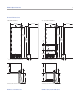
Model Specifications 4 Overall Dimensions COLUMN MODELS 27" (686) TALL MODELS 27" (686) 24" (610) 27" (686) 14" (356) 24" (610) 14" (356) 1 5/8" 13/16" (21) (41) 78 9/16" 78 9/16" (1995) (1995) 81" 80" (2057) TO TOP OF OPENNG (2032) TO TOP OF OPENNG 3/8" (10) 1/2" (13) 13 1/4" (337) 10 1/4" 34 1/2" (876) (260) 20 3/8" (518) 9 3/4" 9 3/4" (248) (248) 4" 1/2" (13) ± ADJUSTMENT IN LEVELING LEGS 4" HEIGHT DIMENSIONS ± 1/2" (13) (102) 24" 24" (610) (610) (102) 4 5/8" 4 5/
Model Specifications 5 subzero.
Model Specifications 6 Overall Dimensions DRAWER MODELS 27" (686) 3/8" (10) 1/2" (13) SPECIFICATIONS 24" (610) Shipping Weight 360 (163) 736TR, 736TFI and 736TCI 480 (218) 700BR, 700BF(I) and 700BC(I) 13 1/4" (337) 34 1/2" (876) 10 1/4" (260) 20 3/8" (518) 9 3/4" (248) HEIGHT DIMENSIONS ± 1/2" (13) 24" (610) 191/2" (495) 25 7/8" (657) DIMENSIONS WILL VARY WITH PANEL THICKNESS MODELS 700BR, 700BF(I) AND 700BC(I) 4" (102) lbs (kg) IC-27R, IC-27FI, 700TR, 700TFI and 700TCI 190 (86)
Site Preparation 7 subzero.com/specs Opening Dimensions INTEGRATED MODELS IMPORTANT NOTE: The depth of each integrated model is 24" (610) from the front of the unit to its back. Your design may necessitate moving the unit back or cabinets forward to achieve a flush fit. This will require a minimum rough opening depth of 25" (635).
Site Preparation 8 Electrical Requirements The electrical supply should be located within the shaded area shown in the illustrations below. Follow the National Electrical Code and local codes and ordinances when installing the receptacle. A separate circuit, servicing only this appliance is required. A ground fault circuit interrupter (GFCI) is not recommended and may cause interruption of operation.
Site Preparation 9 subzero.com/specs Plumbing Requirements For integrated models with an automatic ice maker, the water supply line should be located through the floor or back wall, within the shaded area shown in the illustrations. Routing the line in these locations will avoid any interference with the anti-tip bracket. Plumbing Requirements 1/4" Water Supply Line OD copper, braided stainless steel or PEX tubing Water Pressure 20–100 psi (1.4–6.
Site Preparation 10 Anti-Tip Bracket Installation WOOD FLOOR APPLICATIONS To prevent the unit from tipping forward and provide a stable installation, the unit must be secured in place with the anti-tip bracket provided with the unit. An anti-tip bracket and hardware is provided with the integrated unit. Placement of the anti-tip bracket is critical to a stable installation. The anti-tip bracket must be installed on a solid base.
Site Preparation 11 subzero.com/specs Anti-Tip Bracket Installation Position the Unit INSTALL CONCRETE WEDGE ANCHORS: 1) Drill a 3/8" (10) diameter hole any depth exceeding the minimum embedment. Clean the hole or continue drilling additional depth to accommodate drill fines. Use a carbide drill bit manufactured within ANSI B94.12-77. 2) Assemble the washer and nut flush with the end of anchor to protect threads.
Integrated Installation 12 Position the Unit Level the Unit Plug the power cord into the grounded electrical outlet. With power applied to the appliance, check for lighting and cooling. Press the UNIT ON/OFF key pad on the control panel (POWER for column models). Refer to the illustrations below. Once you are satisfied that the unit is operating properly, shut off power to the electrical outlet at the circuit breaker and proceed.
Integrated Installation 13 subzero.com/specs Molding Installation Water Line Connection Install the decorative white molding strips to the top and sides of the integrated unit for a finished look. The top molding strip, used on column and tall models, must be installed before the side molding can be attached. The top molding strip is held in place by double-sided velcro. The side molding strips snap into place over brackets attached to the side of the unit.
Integrated Installation 14 Kickplate/Grille Installation Panel Considerations Once the integrated unit is secured, the kickplate/grille can be installed. The mounting bracket may be adjusted slightly forward or back so the kickplate/grille will fit flush with the surrounding area. Refer to the illustration below. The integrated design utilizes custom wood or other decorative panels and handles provided by the customer.
Integrated Installation 15 subzero.
Integrated Installation 16 Panel Considerations DOOR PANEL HEIGHT TOE KICK CLEARANCE The height of the door panel can extend beyond the typical panel height, provided you do not exceed the panel weight limit. The toe kick clearance can vary with the height of the panel. You must keep a minimum space of 4" (102) clear below the bottom edge of the panel for proper venting. In addition, any decorative base molding must be removable and cannot exceed 4" (102) in height.
Integrated Installation 17 subzero.com/specs Panel Installation DOOR PANEL INSTALLATION Remove the two pieces of mounting hardware attached to the front of the door and set aside. Place the door panel lying face down on a protected surface to ensure that the front is not scratched or damaged. Position the plastic template as indicated on the template. One side is for a right-hinge unit and the other side is for a left-hinge unit. Verify that you are using the correct side.
Integrated Installation 18 Panel Installation PANEL BRACKET POSITIONING The illustrations below show placement of panel mounting brackets. Dimensions are based on a 4" (102) toe kick and a 1/8" (3) reveal. A reveal of up to 1/4" (6) is possible, but panel dimensions need to be adjusted accordingly.
Integrated Installation 19 subzero.com/specs Panel Installation DRAWER PANEL INSTALLATION Remove the mounting hardware provided and set aside. As with the door panel, you should work on the back side of each drawer panel to protect the front surface. Position the top edge of the template flush with the top edge of each drawer. For the top drawer, there is only one location for the lower mounting bracket.
Integrated Installation 20 Dual Installations 90° Door Stop Two integrated units may be placed side by side in a dual installation. Panel width dimensions will vary slightly from single installations. A dual installation kit is required for installations with 2" (51) or less space between units. Dual installation kits are available through your authorized Sub-Zero dealer. The door of integrated columns and tall models opens to 105°.
Integrated Installation 21 subzero.com/specs Installation Checklist To ensure a safe and proper installation, the following checklist should be completed by the installer to ensure that no part of the installation has been overlooked. INSTALLATION CHECKLIST Have all packing materials been removed? Turn the unit on.
Service Information 22 Service Information If service is necessary, maintain the quality built into your integrated unit by calling Sub-Zero factory certified service. For the name and number of Sub-Zero factory certified service nearest you, check the contact & support section of our website, subzero.com or call Sub-Zero customer care at 800-222-7820. When calling for service, you will need the model and serial numbers of your unit. Both numbers are listed on the product rating plate.
The information and images in this guide are the copyright property of Sub-Zero, Inc. Neither this guide nor any information or images contained herein may be copied or used in whole or in part without the express written permission of Sub-Zero, Inc. ©Sub-Zero, Inc. all rights reserved. Wolf, Wolf & Design, Wolf Gourmet, W & Design and the color red as applied to knobs are registered trademarks and service marks of Wolf Appliance, Inc.
SUB-ZERO, INC. P. O. BOX 44848 MADISON, WI 53744 7023602 REV-A 12/ 2011 SUBZERO.COM 800.222.