W INE S TORAGE I NSTALLATION I NSTRUCTIONS
S U B - Z E R O W I N E S TO R AG E The importance of the installation of the Sub-Zero Wine Storage unit cannot be overemphasized. Installation should be done by a qualified installer. CONTENTS Models 424 and 424FS Installation 3 Models 427 and 427R Installation 12 Model 430 Installation 24 Installation Checklist 34 Service Information 35 Features and specifications indicated herein and on the website are subject to change at any time without notice. Check our website, subzero.
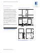
M O D E L S 4 2 4 A N D 4 2 4 F S I N S TA L L A T I O N MODELS 424 A N D 424FS S I T E P R E PA R AT I O N MODELS 424 | 424FS I N S TA L L AT I O N S P E C I F I C AT I O N S The Sub-Zero Model 424FS wine storage unit is designed to be attractive in a stand alone setting. It can also be slid into surrounding cabinetry with clearance dimensions slightly different than the standard built-in Model 424.
M O D E L S 4 2 4 A N D 4 2 4 F S I N S TA L L AT I O N MODELS 424 | 424FS ELECTRICAL R E Q U I R E M E N T S U N PAC K I N G A N D M OV I N G A 115 V AC, 60 Hz, 15 amp circuit breaker and electrical supply are required. A separate circuit, servicing only this appliance, is required. Uncrate the unit, remove its wood base and discard the shipping bolts that hold the wood base to the bottom of the unit. Remove all packing materials and tape.
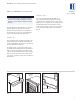
M O D E L S 4 2 4 A N D 4 2 4 F S I N S TA L L A T I O N A N T I - T I P B R AC K E T I N S TA L L A T I O N MODELS 424 | 424FS MODEL 424FS To prevent the unit from tipping forward and provide a stable installation, the unit must be secured in place with the anti-tip bracket. An anti-tip bracket and hardware is provided with the Wine Storage unit. The anti-tip bracket must be installed on a solid base to prevent tipover in case several loaded wine shelves are extended at the same time.
M O D E L S 4 2 4 A N D 4 2 4 F S I N S TA L L AT I O N MODELS 424 | 424FS A N T I - T I P B R AC K E T I N S T A L L A T I O N W O O D F L O O R A P P L I C AT I O N S Installation for Concrete Wedge Anchors: Use the four #12 x 2 1/2" wood screws and the four 1/4" flat washers provided. Drill pilot holes 3/16" (5) diameter maximum, and be sure that the screws penetrate through the flooring material and into the wall plate a minimum of 3/4" (19). Be sure that the screws hold tight.
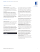
M O D E L S 4 2 4 A N D 4 2 4 F S I N S TA L L A T I O N L O C K I N S TA L L A T I O N IMPORTANT NOTE: If you are adding an accessory lock kit to your Wine Storage unit, it should be installed before you position the unit. Installation instructions are included with the lock kit. For Model 424, the lock is attached to the bottom of the metal door frame. The decorative door panel is not involved in the installation or operation of the lock.
M O D E L S 4 2 4 A N D 4 2 4 F S I N S TA L L AT I O N MODELS 424 | 424FS LEVEL T H E U N I T HOME ALARM C O N N E C T I O N S Using an adjustable wrench or pliers, turn each of the four leveling legs clockwise to raise the unit and counterclockwise to lower the unit. For the location of the leveling legs, see illustration 6 below. Before the kickplate is installed, all necessary wiring connections in the compressor compartment should be completed.
M O D E L S 4 2 4 A N D 4 2 4 F S I N S TA L L A T I O N K I C K P L AT E I N S TA L L A T I O N D O O R PA N E L S – M O D E L 4 2 4 Once the unit is leveled and wiring connections made, the kickplate can be installed. Use the two #10 x 1/2" stainless steel screws that are provided with the kickplate. Refer to illustration 8 below. Model 424 is offered in two design applications; stainless steel (/S) and overlay (/O). Each of these designs are available as a glass door (G) model.
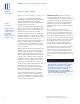
M O D E L S 4 2 4 A N D 4 2 4 F S I N S TA L L AT I O N MODELS 424 | 424FS OV E R L AY D O O R P A N E L S O V E R L AY G L A S S D O O R – M O D E L 4 2 4 PA N E L DESIGN Additional panel design information can be found in the Sub-Zero Design Guide. Check our website at subzero.com. Inspect the door panel for the minimum 5/8" (16) thickness, the finished inside edge and the 10 lbs (5 kg) weight limit. See the Wine Storage section of the Sub-Zero Design Guide for additional panel information.
M O D E L S 4 2 4 A N D 4 2 4 F S I N S TA L L A T I O N HINGE A D J U S T M E N T IMPORTANT NOTE: Install screws in all the mounting holes in the door frame. The nature of the door panel with a narrow outer rim and no connecting center member requires the support provided by the glass door. After the door panel installation is complete, apply the cover patches or plugs provided over the holes on the inside surface of the door.
M O D E L S 4 2 7 A N D 4 2 7 R I N S TA L L AT I O N MODELS 427 | 427R MODELS 427 A N D 427R I N S TA L L A T I O N S P E C I F I C A T I O N S S I T E P R E PA R AT I O N Make sure that the finished rough opening where the Wine Storage unit is to be installed is properly prepared. Refer to the Installation Specifications illustration for rough opening dimensions, door swing clearance and electrical placement for Models 427 and 427R.
M O D E L S 4 2 7 A N D 4 2 7 R I N S TA L L A T I O N ELECTRICAL R E Q U I R E M E N T S U N PAC K I N G A N D M OV I N G A 115 V AC, 60 Hz, 15 amp circuit breaker and electrical supply are required. A separate circuit, servicing only this appliance, is required. Uncrate the unit, remove its wood base and discard the shipping bolts that hold the wood base to the bottom of the unit. Remove all packing materials and tape.
M O D E L S 4 2 7 A N D 4 2 7 R I N S TA L L AT I O N MODELS 427 | 427R A N T I - T I P B R AC K E T I N S T A L L A T I O N W O O D F L O O R A P P L I C AT I O N S Use the six #12 x 2 1/2" wood screws and the six 1/4" flat washers provided. Drill pilot holes 3/16" (5) diameter maximum, and be sure that the screws penetrate through the flooring material and into the wall plate a minimum of 3/4" (19). Be sure that the screws hold tight. Refer to illustration 1 below.
M O D E L S 4 2 7 A N D 4 2 7 R I N S TA L L A T I O N POSITION T H E U N I T MODELS 427 | 427R Installation for Concrete Wedge Anchors: 1) Drill a 3/8" (10) diameter hole any depth exceeding the minimum embedment. Clean the hole or continue drilling additional depth to accommodate drill fines. Use a carbide drill bit manufactured within ANSI B94.12-77. 2) Assemble the washer and nut flush with the end of anchor to protect threads.
M O D E L S 4 2 7 A N D 4 2 7 R I N S TA L L AT I O N MODELS 427 | 427R POSITION T H E U N I T IMPORTANT NOTE: If you are adding an accessory lock kit to your Model 427 or 427R, the catch should be installed at the top of appliance cabinet before you position the unit. See Lock Installation on page 23. Installation instructions are included with the lock kit. Remove the decorative top and side moldings and the kickplate / grille of the Wine Storage unit.
M O D E L S 4 2 7 A N D 4 2 7 R I N S TA L L A T I O N MODELS 427 | 427R LEVEL T H E U N I T M O L D I N G I N S TA L L AT I O N Level the unit by turning the front leveling legs clockwise to raise the unit, or counterclockwise to lower it. To assist you in adjusting the front leveling legs up or down, use a standard screwdriver blade and place it in the front leveling leg as shown in illustration 4 below.
M O D E L S 4 2 7 A N D 4 2 7 R I N S TA L L AT I O N MODELS 427 | 427R OT H E R W I R I N G C O N N E C T I O N S Before the kickplate / grille is installed, all necessary wiring connections in the compressor compartment should be completed. OPTIONAL COMPONENTS Optional installation components are available through your Sub-Zero dealer, or call Sub-Zero at 800-222-7820. You can also visit our website at subzero.com.
M O D E L S 4 2 7 A N D 4 2 7 R I N S TA L L A T I O N K I C K P L AT E / G R I L L E I N S TA L L A T I O N Once the unit is leveled and wiring connections made, the kickplate / grille can be installed. IMPORTANT NOTE: The kickplate / grille must be removed for servicing. The floor cannot interfere with removal. The louvered section of the kickplate / grille must not be covered so as to prevent air circulation.
M O D E L S 4 2 7 A N D 4 2 7 R I N S TA L L AT I O N MODELS 427 | 427R PA N E L DESIGN Additional panel design information can be found in the Sub-Zero Design Guide. Check our website at subzero.com. S TA I N L E S S S T E E L D O O R P A N E L OV E R L AY G L A S S D O O R P A N E L Before installing the stainless steel door panel, check the panel carefully. Options are available for kickplate / grille height, overall height, door swing and door lock.
M O D E L S 4 2 7 A N D 4 2 7 R I N S TA L L A T I O N MODELS 427 | 427R With the Wine Storage unit secured in position and the door closed, the panel is held in the desired position on the door and rapped by hand from the front, putting center marks on the rear surface of the panel. If the door panel is made of such a material that pre-drilling is needed, all of the mounting holes should be marked. If not, only enough holes to hold the panel in place temporarily, are necessary.
M O D E L S 4 2 7 A N D 4 2 7 R I N S TA L L AT I O N MODELS 427 | 427R MODEL 427R D R AW E R PA N E L S IMPORTANT NOTE: Drawer panels for Model 427R must be a minimum of 5/8" (16) thick and cannot exceed 12 lbs (5 kg) for each panel. PA N E L DESIGN Additional panel design information can be found in the Sub-Zero Design Guide. Check our website at subzero.com. With the two brackets in place on the drawer panel, engage the top dog-ear bracket first and then the lower bracket onto the protruding screws.
M O D E L S 4 2 7 A N D 4 2 7 R I N S TA L L A T I O N F I N I S H E D W O O D S I D E PA N E L S L O C K I N S TA L L AT I O N Side panels for Models 427 and 427R are not attached to the unit. You must securely fasten the panels to adjacent cabinets and floor. For Models 427 and 427R, the accessory lock is attached to the decorative door panel through a field-drilled hole in the panel. The catch should be installed on the top of appliance cabinet before the unit was moved into position.
M O D E L 4 3 0 I N S TA L L A T I O N I N S T R U C T I O N S M O D E L 430 M O D E L 4 3 0 I N S TA L L A T I O N S I T E P R E PA R AT I O N I N S TA L L A T I O N S P E C I F I C A T I O N S Make sure that the finished rough opening where the Wine Storage unit is to be installed is properly prepared. Refer to the Installation Specifications illustration for rough opening dimensions, door swing clearance and electrical placement for Model 430.
M O D E L 4 3 0 I N S TA L L A T I O N I N S T R U C T I O N S ELECTRICAL R E Q U I R E M E N T S U N PAC K I N G A N D M OV I N G A 115 V AC, 60 Hz, 15 amp circuit breaker and electrical supply are required. A separate circuit, servicing only this appliance, is required. Uncrate the unit, remove its wood base and discard the shipping bolts that hold the wood base to the bottom of the unit. Remove all packing materials and tape.
M O D E L 4 3 0 I N S TA L L A T I O N I N S T R U C T I O N S M O D E L 430 GRILLE R E M O VA L ANTI-TIP B L O C K I N G K I T In order to prevent damage to the grille and to access the power cord, the top grille assembly should be removed prior to moving the unit. Framed grille: Remove three counter-sunk grille screws at the bottom of the grille and cut the red nylon shipping strap. NOTE: Grille screws are accessed with the door open.
M O D E L 4 3 0 I N S TA L L A T I O N I N S T R U C T I O N S L O C K I N S TA L L A T I O N M O D E L 430 IMPORTANT NOTE: If you are adding an accessory lock kit to your Wine Storage unit, it should be installed before you position the unit. Installation instructions are included with the lock kit. For Model 430, the lock is attached to the bottom of the metal door frame. The decorative door panel is not involved in the installation or operation of the lock.
M O D E L 4 3 0 I N S TA L L A T I O N I N S T R U C T I O N S M O D E L 430 HOME ALARM C O N N E C T I O N S K I C K P L AT E A N D G R I L L E Before the kickplate and grille are installed, all necessary wiring connections in the compressor compartment should be completed. After the unit has been leveled, make sure the drain pan is installed properly and install the kickplate. Refer to illustration 8 below.
M O D E L 4 3 0 I N S TA L L A T I O N I N S T R U C T I O N S DOOR PA N E L S FRAMED D O O R PA N E L Model 430 is offered in three design applications; stainless steel (/S), framed (/F) and overlay (/O). Each of these designs is available as a glass door (G) model. Inspect the door panel for the minimum 5/8" (16) thickness, the required 1/4" (6) routing around the perimeter, as shown in illustration 11 on page 30, and the finished inside edge. The door panel has a weight limit of 25 lbs (11 kg).
M O D E L 4 3 0 I N S TA L L A T I O N I N S T R U C T I O N S M O D E L 430 PA N E L DESIGN Additional panel design information can be found in the Sub-Zero Design Guide. Check our website at subzero.com. FRAMED D O O R PA N E L OV E R L AY D O O R P A N E L Install the #8 x 5/8" screws through the back of the glass door frame into the door panel. Refer to illustration 11 below. If your customer has chosen an overlay design door and grille panel, the unit will be shipped without handle and hardware.
M O D E L 4 3 0 I N S TA L L A T I O N I N S T R U C T I O N S M O D E L 430 The wine storage unit door is made with a sealed double wall tempered glass core. The drill must not contact this core when drilling. Be sure the hole is centered on the small groove in the front of the door frame and the drill passes squarely through the frame. If you are inexperienced with drilling, fasten the handle from the rear of the door panel only.
M O D E L 4 3 0 I N S TA L L A T I O N I N S T R U C T I O N S M O D E L 430 S I D E PA N E L I N S TA L L A T I O N If you’re installing a Model 430 with side panels, check with your installer or use one of the following Side Panel Installation Options. Drill three holes equidistant in a vertical section of the aluminum frame, and install pan head screws. Do not drill through model and serial number plate. Anchor the side panel with decorative screws or finishing nails from a local hardware store.
M O D E L 4 3 0 I N S TA L L A T I O N I N S T R U C T I O N S ANCHOR T H E U N I T M O D E L 430 After door and side panels have been installed, the unit has been leveled and door adjustment completed, anchor the unit to the opening. This will assure a proper fit and a secure installation. The Sub-Zero Anchoring Kit (part #4200900), available from your Sub-Zero dealer, includes the necessary hardware. IMPORTANT NOTE: Be sure to level and square the unit before anchoring it.
M O D E L 4 3 0 I N S TA L L A T I O N I N S T R U C T I O N S M O D E L 430 OPTIONAL COMPONENTS Optional installation components are available through your Sub-Zero dealer, or call Sub-Zero at 800-222-7820. You can also visit our website at subzero.com. HINGE A D J U S T M E N T I N S TA L L AT I O N C H E C K L I S T IMPORTANT NOTE: The unit must be installed and leveled before adjusting the door hinges. The importance of the installation of the Sub-Zero Wine Storage unit cannot be overemphasized.
S E RV I C E I N F O R M A T I O N S E RV I C E I N F O R M A T I O N I N S TA L L A T I O N C H E C K L I S T Has the packing material been removed? Turn the unit on first, is the unit operating properly? If not, is it plugged in? Is the control turned on? Has the unit been secured in place with an anti-tip bracket or by a secure overhead cabinet or structure? Are front leveling legs extended and making contact with the floor? Is the unit level? Is power cord connected directly to a properly grounded 3-p
SUB-ZERO, INC. 3 7 5 8 6 1 5 R E V- B P. O . B O X 4 4 1 3 0 12 / 2007 MADISON, WI 53744-4130 800-222-7820 SUBZERO.