II _,!STALLATION STRUCTIONS IIIII III II III I I SUB-ZERO I I I IiI' '111
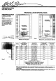
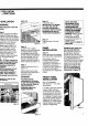
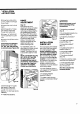
I I I IIIII IIIIIII I I I IIIII IIIIII I I HIII PRI -INSTALLATION INSTRUCTIONS PRE-INSTALLATION SPECIFICATIONS PREPARATION FOR INSTALLATION Step 1 Prepare the finished rough opening to accept the installation of the Sub-Zero. NOTE: Carefully read the "Pre-lnstallation Specifications" chart below. LOCATE ELECTRICAL OUTLET WITHIN TOP St-_DED _ NE,, WITHIN BOTIOM _DAREA =W" LOCATE_ SUPPLY SHUT OFF V4LV£ A '_ /" A .
i I ii I ! I I -INSTALLATION TRUCTIONS | ,REA REPARATION Do not use an extension cord, or two prong adapter. Electrical ground is required on this appliance. ;tep 2 A/hen units are installed side 3y side, a separating filler strip s recommended. The filler _trip width should be added to he finished rough opening dimension. A filler strip must _lso be used when units are nstalled hinge to hinge. IMPORTANT." For proper operation and use the door must open a minimum of 90 °.
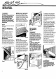
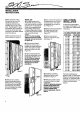
INSTALLATION INSTRUCTIONS IAwARNING I To reduce the possibility of the unit tipping forward, you must reposition the front levelers to make contact with the floor. You will have to extend these legs when the unit is finally positioned. MODELS 501F AND 501R To remove the 501 grille, remove two (black) screws located in the lowest louver in the grille. Tilt the bottom of the grille out and away, it will release from the top of the grille. There is no grille spring on 501 Series. See Figure 8.
t '° TALLATION ,.. TRUCTIONS MODEL 590 iSTALLATION Step 12 Install grille, step 7. IMPORTANT'. For Models 511, 532, 542, 550, 561 and 590, reverse step 7 procedure. NOTE: If using panelized grille refer to "Grille Panel Installation." _WARNING ] ;hut-off power to the wall )utlet. ;tep 9 Jnit is equipped with rollers. )lug into 15 amp grounded )utletand roll unit into desired )osition under the wood block )r soffit and connect icemaker rater line to unit.
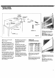
llllllllll I III II IIIIII INSTALLATION INSTRUCTIONS B) With standard Phillips screwdriver, remove door handle on freezer and refrigerator door (the door handles also act as a door trim). The Models 511 and 550 freezer door handle isw on the top of the door and removed in the same manner described above. C) Slide panel into frame on door as shown in Figure 17. MODEL 590 A) To install panels on the Model 590, the door handle and door handle trim must first be removed.
I I IIIIII II II I I iF'NSTALLATION .,qSTRUCTIONS 11" GRILLE ONLY 532 & SN 11" THRU T$" GRILLE ALL OTHER MODELS P_ ,l-:z-o.-0 SCREW GROMMET pin .1_,o.o, 3-o UPPER G_LLE SCREW t i Figure 21 LOWER GRILLE SCREW Figure 20 C) Slide panel into position in grille frame as shown in Figure 22. NOTE: When using _/4" or less, a filler is necessary. -,-]_ ,4) Remove Iouvered grille. Refer to step 7. B) Open the door(s) and attach template provided with panel grille installation kit.
INSTALLATION INSTRUCTIONS r/d" SIDE PANEL INSTALLATION Anchor the side panel with decorative headed screws (as shown) or finishing nails can be used. The screws/ nails must be obtained from your local hardware supply store. NOTE: We do not recommend the use of adhesives. If side panels are being utilized, please check with your installer for installation methods or you may use one of the side panel installation methods shown in Figure 23.
i'"'ISTALLATION" ' ,,4STRUCTIONS 2) Using the Loctite on the screws, install all 3 Chicago Screw Posts. HINGE ADJUSTMENT 3) Inspect the units for level again. Step 16 If the doors are out of adjustment, the top or bottom hinge may be adjusted by removing and discarding the two small shipping screws. See Figure 26. The top door hinges can be adjusted left to right and in or out by loosening the three allen head screws. The bottom door hinge is equipped with two adjustment allen head screws.
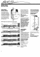
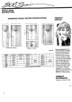
IIIIIIIIIII I lU INSTALLATION INSTRUCTIONS STANDARD HANDLE RECESS SPECIFICATIONS I" A _ I------- PRODUCT SERVICE ,! T ± 14" T c 14" ± =: !i:_i MODELS _]_ MODELS 532, 501F ,4ND 501R 542 AND 561 MODELS 511 AND 550 Figure 28 MODEL 532 542 561 511 550 A (WIDTH) 1715115" 155/8" 145/8" 281/s" 341/8" 501F 501R 34Ve" 34V8" 590 B (WIDTH) 2711116" 24" 191/5" C (HEIGHT) 6711/16" 6711/16" 6711/16" 481/16" 481/15" D E F 385/32 .
LISTAL_LATION ,.4STRUCTIONS _ECOMMENDATIONS :OR RAISED =ANELS _ecause of different door panel Jesigns, routing, recessing, or Jseof optional extended handles nay be necessary for finger "learance when using raised )anels greater than 114"total hickness. (50# per door panel naximum weight limit.) _ee Figure 28 for location of _ffset when using specific "outing for grip area only. figure 29 is actual size top ,iew of standard full length _andle and panel.
THINK SAFETYt If you are storing or disposing of your old refrigerator, please do it safely. Read the enclosed safety booklet from the Association of Home Appliance Manufacturers. CHILD ENTRAPMENT ACCIDENTS CAN BE TRAGIC! SUB-Z SUB SUB-ZERO FREEZER CO., INC. FORM NO. 3-75-216-16 P.O. BOX 44130, MADISON, Wl 53744-4130 PRINTED IN U.S.A.