PRO 48 Refrigeration Installation Guide
PRO 48 REFRIGERATION Contents Important Note 3 PRO 48 Refrigeration 4 Opening Dimensions To ensure this product is installed and operated as safely and efficiently as possible, take note of the following types of highlighted information throughout this guide: 5 Electrical IMPORTANT NOTE highlights information that is especially 5 Plumbing important. 6 Preparation CAUTION indicates a situation where minor injury or product damage may occur if instructions are not followed.
PRO 48 REFRIGERATION Product Information Tools and Materials Important product information including the model and serial number are listed on the product rating plate. The rating plate is located inside the cabinet, to the left of the upper freezer drawer. Refer to the illustration below. • Screwdrivers—standard, Phillips and Torx. If service is necessary, contact Sub-Zero factory certified service with the model and serial number.
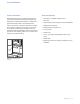
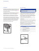
SITE PREPARATION Opening Dimensions STANDARD AND FLUSH BUILT-IN INSTALLATIONS D OPENING DEPTH TOP VIEW W H OPENING WIDTH OPENING HEIGHT SIDE VIEW OPENING Standard Flush 4 | FRONT VIEW W H D 47 1/2" (1206) 83 3/4" (2127) 24" (610) 48" (1219) 84 1/8" (2137) 26" (660) Sub-Zero Customer Care 800.222.7820 For standard built-in installations, the face frame will extend 2" (51) beyond cabinetry. In flush installations, the face frame will be flush with surrounding cabinetry.
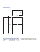
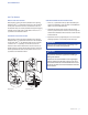
SITE PREPARATION Electrical Plumbing Installation must comply with all applicable electrical codes. Installation must comply with all applicable plumbing codes. The electrical supply should be located within the shaded area shown in the illustration below. A separate circuit, servicing only this appliance is required. A ground fault circuit interrupter (GFCI) is not recommended and may cause interruption of operation.
SITE PREPARATION Preparation Anti-Tip Bracket Uncrate the unit and inspect for damage. Remove the wood base and discard shipping bolts and brackets. Remove and recycle packing materials. Do not discard the kickplate, antitip bracket and hardware. Completely retract the front leveling legs to allow the unit to be moved into position. The front and rear leveling legs can be adjusted from the front once the unit is in position.
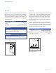
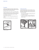
SITE PREPARATION Anti-Tip Bracket WOOD FLOOR APPLICATION CONCRETE WEDGE ANCHOR INSTALLATION: After properly locating the anti-tip bracket in the opening, drill pilot holes 3/16" (5) diameter maximum in the wall studs or wall plate. Use the #12 screws and washers to secure the bracket. Verify the screws penetrate through the flooring material and into wall studs or wall plate a minimum of 3/4" (19). Refer to the illustration below.
INSTALLATION Placement CAUTION Before moving the unit into position, secure doors and drawers closed and protect any finished flooring. Use an appliance dolly to move the unit near the opening. If the unit has been on its back or side, it must stand upright for a minimum of 24 hours before connecting power. Plug the power cord into the grounded outlet and roll the unit into position. Verify the anti-tip bracket is properly engaged. Water Line Approximately 3' (.
INSTALLATION Alignment DOOR ADJUSTMENT DRAWER ADJUSTMENT To make adjustments, remove door and door stop, then slightly loosen the two upper hinge screws. Use the Allen wrench provided to turn adjustment screw to adjust hinge. Refer to the illustration below. Reinstall door and check alignment. Repeat until door is properly aligned. Vertical adjustment | Loosen the three mounting screws. Refer to the illustration below.
INSTALLATION Completion Install the grille assembly and check for proper fit. Reconnect the network cable. Refer to page 6. Attach the network cable to the grille using cable ties provided. Reinstall the drain pan and verify it is in the proper position. Install the kickplate using screws to attach it to brackets on the inside of each roller base. Refer to the illustration below. The kickplate must be removable for service. The floor cannot interfere with removal. Install leg covers.
INSTALLATION Completion 90° DOOR STOP The doors of all models open to 135°. For installations where the door opening must be limited, an optional 90° door stop kit is available through an authorized Sub‑Zero dealer. For local dealer information, visit the find a showroom section of our website, subzero.com. WARNING Follow all city and state laws when storing, recycling or discarding unused refrigerators and freezers.
UNIDAD DE REFRIGERACIÓN PRO 48 Contenido Aviso importante 3 Unidad de refrigeración PRO 48 4 Dimensiones de abertura Para garantizar que este producto sea instalado y operado de la forma más segura y eficiente posible, tome nota de los siguientes tipos de información resaltada en esta guía: 5 Instalación eléctrica AVISO IMPORTANTE resalta la información que es especial- 5 Plomería mente importante.
UNIDAD DE REFRIGERACIÓN PRO 48 Información del producto Herramientas y materiales La información importante del producto, incluido el modelo y número de serie de la unidad, se encuentran en la placa de datos del producto. La placa de datos se encuentra dentro del gabinete, a la izquierda del cajón superior del refrigerador. Consulte la siguiente ilustración. • Destornilladores: estándar, Phillips y Torx.
PREPARACIÓN DEL SITIO Dimensiones de abertura INSTALACIONES INTEGRADAS ESTÁNDAR Y EMPOTRABLES TOP VIEW VISTA SUPERIOR OPENING PROFUNDIDAD DEPTH DE LA ABERTURA OPENING PROFUNDIDAD DE LADEPTH ABERTURA OPENING ANCHURA DE WIDTH ABERTURA OPENING ALTURA DE HEIGHT LA ABERTURA SIDE VIEW VISTA LATERAL FRONT VIEW VISTA FRONTAL APERTURA ESTÁNDAR EMPOTRABLE Ancho 471/2" (1206) 48" (1219) Altura 833/4" (2127) 841/8" (2137) 24" (610) 26" (660) Profundidad* 4 | Atención al cliente de Sub-Zero 800.222.
PREPARACIÓN DEL SITIO Instalación eléctrica Plomería La instalación debe cumplir con todos los códigos eléctricos vigentes. La instalación debe cumplir con todos los códigos de plomería vigentes. El suministro eléctrico debe colocarse dentro del área sombreada que se muestra en la siguiente ilustración. Es necesario un circuito independiente, que dé servicio únicamente a este aparato.
PREPARACIÓN DEL SITIO Preparación Soporte antivuelco Desembale la unidad e inspeccione si tiene algún daño. Retire la base de madera y deseche los pernos y soportes de transporte. Retire y recicle los materiales de embalaje. No deseche el zócalo, el soporte antivuelco ni las piezas de montaje. Repliegue completamente las patas niveladoras delanteras para que pueda mover la unidad a su posición.
PREPARACIÓN DEL SITIO Soporte antivuelco APLICACIÓN EN SUELO DE MADERA INSTALACIÓN DE LAS ANCLAS DE CUÑA PARA CONCRETO: Después de ubicar apropiadamente el soporte antivuelco en la abertura, taladre los orificios guía con un diámetro máximo de 3/16" (5) en los travesaños o en la placa de la pared. Utilice los tornillos #12 y las arandelas para sujetar el soporte. Compruebe que los tornillos penetren a través del material del suelo y los travesaños o la placa de la pared 3/4" (19) como mínimo.
INSTALACIÓN Colocación PRECAUCIÓN Antes de mover la unidad a su posición, asegúrese de que las puertas y cajones estén cerrados y proteja cualquier suelo con acabado. Utilice una plataforma rodante para mover la unidad cerca de la abertura. Si la unidad ha estado o está acostada o de lado, debe ponerla de pie y dejarla así durante un mínimo de 24 horas antes de conectarla al suministro eléctrico. Conecte el cable de alimentación a la conexión a tierra y coloque la unidad en su sitio.
INSTALACIÓN Alineación AJUSTE DE LA PUERTA AJUSTE DE LOS CAJONES Para realizar cualquier ajuste, retire la puerta y el tope de la puerta y afloje ligeramente los dos tornillos de la bisagra superior. Con la llave Allen incluida gire el tornillo para ajustar la bisagra. Consulte la siguiente ilustración. Vuelva a instalar la puerta y verifique la alienación. Repita los pasos hasta que la puerta esté alineada correctamente. Ajuste vertical | Afloje los tres tornillos de montaje.
INSTALACIÓN Finalización Instale el conjunto de la rejilla y verifique que se ajuste adecuadamente. Vuelva a conectar el cable de red. Consulte la página 6. Una el cable de red a la rejilla con los amarracables que vienen incluidos. Vuelva a instalar la bandeja de drenaje y compruebe que esté bien puesta. Instale el zócalo y sujételo a los soportes con los tornillos dentro de cada una de las bases rodantes. Consulte la siguiente ilustración.
INSTALACIÓN Finalización TOPE PARA PUERTA A 90° Las puertas de todos los modelos abren a 135°. Las instalaciones en las que se debe limitar la abertura de la puerta disponen de un juego de topes de 90° para puertas a través de un distribuidor autorizado de Sub‑Zero. Para obtener más información acerca de los distribuidores locales, visite la sección para encontrar una sala de exhibición de nuestro sitio web, subzero.com.
RÉFRIGÉRATION PRO 48 Table des matières Remarque importante 3 Réfrigération PRO 48 4 Dimensions de l’ouverture 5 Électricité Pour s’assurer que ce produit est installé et utilisé en toute sécurité et aussi efficacement que possible, prenez note des types de renseignement mis en évidence tout au long de ce guide : 5 Plomberie REMARQUE IMPORTANTE met en évidence des renseigne- 6 Préparation ments qui sont particulièrement importants.
RÉFRIGÉRATION PRO 48 Renseignements sur le produit Outils et matériaux Des renseignements importants sur le produit, y compris les numéros de modèle et de série de votre unité, se trouvent sur la plaque signalétique du produit. La plaque signalétique est située à l’intérieur de l’armoire à la gauche du tiroir supérieur du congélateur. Reportez-vous à l’illustration ci-dessous. • Tournevis—standard, cruciforme et Torx.
PRÉPARATION DU SITE Dimensions de l’ouverture INSTALLATIONS INTÉGRÉES STANDARDS ET À AFFLEUREMENT VUEVIEW DE TOP DESSUS PROFONDEUR OPENING DE DEPTH L’OUVERTURE PROFONDEUR DE OPENING DEPTH L’OUVERTURE HAUTEUR OPENINGDE HEIGHT L’OUVERTURE LARGEUR OPENINGDE WIDTH L’OUVERTURE SIDE VIEW VUE DE PROFIL OUVERTURE FRONT VUE DE VIEW FACE STANDARD À AFFLEUREMENT Largeur 471/2 po (1 206) 48 po (1 219) Hauteur 833/4 po (2 127) 841/8 po (2 137) 24 po (610) 26 po (660) Profondeur* 4 | Service à la cl
PRÉPARATION DU SITE Électricité Plomberie L’installation doit se conformer à tous les codes électriques applicables. L’installation doit se conformer à tous les codes de plomberie applicables. L’alimentation électrique doit se trouver à l’intérieur de la zone ombragée indiquée dans l’illustration ci-dessous. Un circuit séparé servant uniquement cet appareil est requis. Un disjoncteur de fuite de terre (GFCI) n’est pas recommandé et peut interrompre le fonctionnement.
PRÉPARATION DU SITE Préparation Support antibasculement Sortez l’unité de la boîte et examinez-la pour vous assurer qu’elle n’est pas endommagée. Retirez la base en bois et jetez les boulons et les supports d’expédition. Retirez et recyclez les matériaux d’emballage. Ne jetez pas la plaque de protection, le support antibasculement et la quincaillerie. Rentrez complètement les pieds de nivellement avant afin de pouvoir déplacer l’unité jusqu’à son emplacement.
PRÉPARATION DU SITE Support antibasculement APPLICATION SUR UN PLANCHER EN BOIS INSTALLATION DE LA CALE D’ANCRAGE POUR BÉTON : Après avoir correctement repéré les supports antibasculement dans l’ouverture préliminaire, percez des avant-trous de 3/16 po (5) de diamètre au maximum dans les poteaux muraux ou la plaque murale. Utilisez les vis et les rondelles n° 12 pour fixer les supports.
INSTALLATION Mise en place MISE EN GARDE Avant de mettre l’unité en place, sécurisez les portes et les tiroirs en position fermée et protégez tout plancher fini. Utilisez un chariot à appareil pour déplacer l’unité près de l’ouverture. Si l’unité a été posée sur le dos ou le côté, elle doit être mise debout pendant au moins 24 heures avant de relier l’alimentation. Branchez le cordon d’alimentation dans une prise mise à la terre et roulez l’unité en place.
INSTALLATION Alignement RÉGLAGE DE LA PORTE RÉGLAGE DU TIROIR Pour effectuer des réglages, retirez la porte et la butée de porte, puis desserrez légèrement les deux vis de la charnière supérieure. Utilisez la clé Allen fournie pour tourner la vis de réglage pour ajuster la charnière. Reportez-vous à l’illustration ci-dessous. Réinstallez la porte et vérifiez l’alignement. Répétez jusqu’à ce que la porte soit correctement alignée. Réglage vertical | Desserrez les trois vis de montage.
INSTALLATION Achèvement Installez l’assemblage de la grille et vérifiez son ajustement. Rebranchez le câble de réseau. Reportez-vous à la page 6. Fixez le câble de réseau à la grille au moyen des attaches de câble fournies. Réinstallez la cuvette d’égouttement et vérifiez qu’elle se trouve à la bonne position. Installez la plaque de protection au moyen de vis pour la fixer aux supports situés à l’intérieur de chaque base de roulettes. Reportez-vous à l’illustration ci-dessous.
INSTALLATION Achèvement BUTÉE DE PORTE DE 90° Les portes de tous les modèles s’ouvrent jusqu’à 135°. Pour les installations où l’ouverture de la porte doit être limitée, une trousse pour butée de porte de 90° en option est offerte par un dépositaire Sub‑Zero autorisé. Pour obtenir des renseignements sur votre dépositaire local, visitez la section salle d’exposition de notre site Web, subzero.
SUB-ZERO, INC. P.O. BOX 44848 MADISON, WI 53744 7028630 REV-A 5 / 2013 SUBZERO.COM 800.222.