DESIGN GUIDE REVISED 8 / 2019
TA B L E O F C O N T E N T S 3 C L A S S I C R E F R I G E R AT I O N 40 P R O R E F R I G E R AT I O N 48 D E S I G N E R R E F R I G E R AT I O N 58 WINE STORAGE 90 U N D E R C O U N T E R R E F R I G E R AT I O N 100 SUB-ZERO WARRANTIES Features and specifications are subject to change at any time without notice. Visit subzero.com/specs for the most up-to-date information. Throughout this guide, dimensions may vary by ± 1/8" (3).
C L A S S I C R E F R I G E R AT I O N subzero.
C L AS S IC R EF R I GE RATION Classic Refrigeration For Classic refrigeration, Sub-Zero designers and engineers took a fresh look at everything, inside and out. Exterior refinements include redesigned grilles and lower-profile hinges. Inside, new technology in food preservation makes Classic refrigeration nothing short of revolutionary. C L AS S IC MO DE L S BI-36R BI-36UFD(ID) BI-36RG BI-42UFD(ID) BI-36F BI-36S 4 | Sub-Zero Customer Care 800.222.
C L AS S IC R EF R I GE RATION Specifications INTERIOR CAPACITY— CU FT (L ) A L L R E F R I G E R AT O R / ALL FREE Z E R BI-36R BI-36RG BI-36F OV E R - A N D - U N D E R BI-30U BI-30UG BI-36U(ID) BI-36UG BI-36UFD(ID) BI-42UFD(ID) SI D E - B Y- S I D E BI-36S BI-42S BI-42SID BI-42SD BI-48S BI-48SID BI-48SD REFR FRZR 23.5 (665) 23.4 (663) 22.7 (643) REFR FRZR 13.2 (374) 13.1 (371) 16.4 (464) 16.3 (462) 15.7 (445) 17.9 (507) 4.2 (119) 4.2 (119) 5.3 (150) 5.3 (150) 5.3 (150) 6.
C L AS S IC R EF R I GE RATION Classic Design Options F R AMED O VER LAY Choose framed custom door panels that contrast with the stainless steel full-length handles and louvered grille (shown). The framed application is an overlay model with framed design features. Panel, grille, and handle options are available. Custom overlay door panels can be combined with unique handle hardware for design flexibility. Shown with the pro handle option to complement Wolf ranges.
C L AS S IC R EF R I GE RATION Classic Design Options F LUS H INS ET S TA I N LES S S TEEL The flush inset design option allows for flush door and grille panels and custom handle hardware. Shown with the tubular handle option to match Wolf built-in ovens. The flush inset application is an overlay model with flush inset panels. Customize with panel, grille, and handle options. Stainless steel models require no customization. To complement the look of Wolf ranges, choose the pro handle option (shown).
C L AS S IC R EF R I GE RATION Overall Dimensions A L L R EF R IG ER ATOR / AL L FRE E Z E R 26 3/16" (665) 36" (914) 84" (2134) 73 3/4" (1873) HEIGHT DIMENSIONS ± 1/2" (13) 4" (102) 23 7/8" (606) 14 1/8" (359) 37 1/4" (946) 2 3/8" (60) Model BI-36R, BI-36RG, BI-36F 8 | Sub-Zero Customer Care 800.222.7820 23 7/8" (606) Overall dimensions are based on stainless steel models. For flush inset applications, add 1/2" (13) to door clearance dimensions.
C L AS S IC R EF R I GE RATION Overall Dimensions O VER -AND-UND E R 26 3/16" (665) 30" (762) 26 3/16" (665) 36" (914) 84" 84" (2134) (2134) 50 3/4" 50 3/4" (1289) (1289) 23" 23" (584) (584) HEIGHT DIMENSIONS ± 1/2" (13) 4" (102) HEIGHT DIMENSIONS ± 1/2" (13) 23 7/8" (606) (606) (606) 14 1/8" 12 1/8" (308) (600) 23 7/8" (606) 23 7/8" 23 7/8" 23 5/8" 4" (102) (359) 311/4" (796) 23 5/8" (600) 37 1/4" (946) 2 3/8" (60) 2 3/8" (60) Model BI-30U, BI-30UG Model BI-36U(ID), BI-
C L AS S IC R EF R I GE RATION Overall Dimensions O VER -AND-UND E R 26 3/16" (665) 36" (914) 26 3/16" (665) 42" (1067) 84" 84" (2134) (2134) 50 3/4" 50 3/4" (1289) (1289) 23" 23" (584) HEIGHT DIMENSIONS ± 1/2" (13) (584) 4" (102) HEIGHT DIMENSIONS ± 1/2" (13) 23 7/8" (606) 23 7/8" 4" (102) 23 7/8" (606) (606) 8" 9" (203) (229) 23 5/8" 191/2" 23 5/8" (495) (600) (600) 221/4" (565) 2 3/8" (60) Model BI-36UFD(ID) 10 | Sub-Zero Customer Care 800.222.
C L AS S IC R EF R I GE RATION Overall Dimensions S I DE-B Y-S IDE 26 3/16" (665) 36" (914) 84" 84" (2134) (2134) 73 3/4" 73 3/4" (1873) (1873) HEIGHT DIMENSIONS ± 1/2" (13) 26 3/16" (665) 42" (1067) 4" (102) HEIGHT DIMENSIONS ± 1/2" (13) 23 7/8" (606) 4" (102) 23 7/8" 23 7/8" (606) (606) 7 1/4" (184) 7 1/2" (191) 8 3/4" (222) 23 7/8" (606) 10 3/8" (264) 26 1/4" 221/4" (668) (565) 2 3/8" (60) 2 3/8" (60) Model BI-36S Model BI-42S(ID), BI-42SD subzero.
C L AS S IC R EF R I GE RATION Overall Dimensions S I DE-B Y-S IDE 26 3/16" (665) 48" (1219) 84" (2134) 73 3/4" (1873) HEIGHT DIMENSIONS ± 1/2" (13) 4" (102) 23 7/8" (606) 8 3/8" (213) 11 5/8" (295) 30" (762) 2 3/8" (60) Model BI-48S(ID), BI-48SD 12 | Sub-Zero Customer Care 800.222.
C L AS S IC R EF R I GE RATION Specifications SHIPPING WEIGHT A L L R E F R I G E R AT O R / ALL FREE Z E R BI-36R BI-36RG BI-36F OV E R - A N D - U N D E R BI-30U BI-30UG BI-36U(ID) BI-36UG BI-36UFD(ID) BI-42UFD(ID) SI D E - B Y- S I D E BI-36S BI-42S BI-42SID BI-42SD BI-48S BI-48SID BI-48SD L B (KG ) 420 (191) 430 (195) 406 (184) L B (KG ) 462 (210) 476 (216) 515 (234) 529 (240) 529 (240) 582 (264) L B (KG ) 538 (244) 582 (264) 608 (276) 608 (276) 630 (286) 656 (298) 656 (298) Shipping weights ar
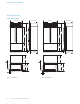
C L AS S IC R EF R I GE RATION Opening Dimensions S TANDAR D INS TAL L ATION 24" (610) OPENING DEPTH 3/4" (19) TYPICAL 3 1/2" (89) FINISHED RETURN TOP VIEW W FRAMELESS CABINETRY 3/4" (19) TYPICAL 3 1/2" (89) FINISHED RETURN 83 3/4" W (2127) OPENING HEIGHT OPENING WIDTH SIDE VIEW FILLER W FRAMED CABINETRY FRONT VIEW NOTE: 3 1/2" (89) finished returns will be visible and should be finished to match cabinetry. Shaded line represents profile of unit.
C L AS S IC R EF R I GE RATION Opening Dimensions F LUS H INS ET INSTAL L ATION 26 3/16" (665) FLUSH INSET DEPTH 5 11/16" 3 1/2" 2 3/16" (56) (89) (145) FINISHED RETURN FINISHED CLEATS TOP VIEW CLEAT 3/4" (19) TYPICAL W FRAMELESS CABINETRY 11/4" 1/4" (6) (32) 5 11/16" 3 1/2" (89) (145) FINISHED RETURN SIDE VIEW 84" W (2134) FLUSH INSET HEIGHT FLUSH INSET WIDTH CLEAT FILLER 3/4" (19) TYPICAL W FRAMED CABINETRY FRONT VIEW NOTE: 3 1/2" (89) finished returns and shaded areas will be visib
C L AS S IC R EF R I GE RATION Opening Dimensions D U AL S TANDARD INSTAL L ATION 24" (610) OPENING DEPTH 3/4" (19) TYPICAL 3 1/2" (89) FINISHED RETURN TOP VIEW W FRAMELESS CABINETRY 3/4" (19) TYPICAL 3 1/2" (89) FINISHED RETURN 83 3/4" W (2127) OPENING HEIGHT OPENING WIDTH SIDE VIEW FILLER W FRAMED CABINETRY FRONT VIEW NOTE: 3 1/2" (89) finished returns will be visible and should be finished to match cabinetry. Shaded line represents profile of unit.
C L AS S IC R EF R I GE RATION Opening Dimensions D U AL F LUS H IN SE T INSTAL L ATION 26 3/16" (665) FLUSH INSET DEPTH (56) CLEAT 5 11/16" 3 1/2" 2 3/16" 3/4" (19) (89) (145) FINISHED RETURN FINISHED CLEATS TOP VIEW TYPICAL W FRAMELESS CABINETRY 11/4" 1/4" (6) (32) CLEAT 5 11/16" 3 1/2" (89) (145) FINISHED RETURN 84" W (2134) FLUSH INSET HEIGHT FLUSH INSET WIDTH FILLER 3/4" (19) TYPICAL W FRAMED CABINETRY SIDE VIEW FRONT VIEW NOTE: 3 1/2" (89) finished returns and shaded areas w
C L AS S IC R EF R I GE RATION Electrical Requirements Plumbing Requirements The electrical supply should be located within the shaded area shown in the illustration below. A separate circuit servicing only this appliance is required. A ground fault circuit interrupter (GFCI) is not recommended and may cause interruption of operation. Locate the water supply line within the shaded area shown in the illustration below.
C L AS S IC R EF R I GE RATION Custom Panels For framed, overlay, and flush inset applications, custom door panels must be provided. Handle hardware must also be provided for overlay and flush inset applications. Refer to Panel Requirements below and the charts on pages 22–27 for custom panel dimensions for your specific design application. IMPORTANT NOTE: Do not cover a glass door with a solid panel. Finish all sides of the custom panels.
C L AS S IC R EF R I GE RATION Custom Panels PART IAL F R AME D OPTION PAN EL M O U N TI N G K I T The partial framed kit includes a stainless steel panel for above and below the external dispenser. Refer to the chart below for panel width. The kit is available through an authorized Sub-Zero dealer. For local dealer information, visit the find a showroom section of our website, subzero.com.
C L AS S IC R EF R I GE RATION Custom Panels F LUS H INS ET PA NE L S I C E A N D WATER D I S P EN S ER The flush inset application is an overlay model with flush inset panels. It is not a separate model. For models BI-42SD and BI‑48SD, the refrigerator door panel must include a cutout to accommodate the external dispenser. The bezel will accommodate a 1/4" (6) thick panel for framed applications and a 3/4" (19) thick panel for overlay and flush inset applications.
C L AS S IC R EF R I GE RATION Framed Panel Dimensions H H H H H H H A A H H H H AH A A A A H H H H H H H H A A A H AH AH H A AH A H H H H AH A A A A A A H H B B W W W W W BI-30U, BI-36U(ID) H H H H H W H 35 3/4" (908) 69 9/16" (1767) W H H H H H H 8 15/16" (227) GRI L L E ( O P T I O N A L) H H H H H 35 3/4" (908) BI-36RG A 5 3/16A" A(132) A Stiles / Rails B B B A A 10 5/16" (262) W (1268) W H 29 3/4" (756) 18 11/16" (475) GRI L L E ( O P T I O N A L) Grille Panel
C L AS S IC R EF R I GE RATION WW AA HH WW HH HH BB WW WW WW WW WW Framed Panel Dimensions HH HH HH HH AA BB WW WW BI-36S, BI-42S(ID), BI-48S(ID) WW WW BI-42SD, BI-48SD MODEL BI-36S MODEL BI-48S, BI-48SID, BI-48SD R E F R I G E R AT O R Door Panel W H 19 13/16" (503) 69 9/16" (1767) FREEZER Door Panel W H 15 7/16" (392) 69 9/16" (1767) GRI L L E ( O P T I O N A L) Grille Panel W H 35 3/4" (908) 8 15/16" (227) REFRIGERATOR Door Panel FREEZER Door Panel GRIL L E (O
C L AS S IC R EF R I GE RATION Overlay Panel Dimensions H H H H H H H H H H H AH A H H H H H H H H A A A A A A A A H AH AH H A AH A H H H H AH A A A A A A H H B B W W W W W BI-30U, BI-36U(ID) H H H H H H H H W H 36" (914) 35 1/8" (892) 35 3/4" (908) 69 3/4" (1772) 15/16" (1751) 68 H H H H H 69 9/16" (1767) GRI L L E Overlay Panel Spacer Panel Backer Panel W H 36" (914) A A A 35 1/8" (892) B B 35 3/4" (908) 9 1/4" (235)* 8 5/16" (211) B 8 15/16" (227) BI-36RG Stiles / Rails
C L AS S IC R EF R I GE RATION WW AA HH WW HH HH BB WW WW WW WW WW Overlay Panel Dimensions HH MODEL BI-42S, BI-42SID, BI-42SD HH REFRIGERATOR HH Overlay Panel Spacer Panel Backer Panel HH W H 25 1/16" (637) 24 3/16" (614) 24 13/16" (630) 69 3/4" (1772) 68 15/16" (1751) 69 9/16" (1767) FREEZER Overlay Panel Spacer Panel Backer Panel AA BB WW WW BI-36S, BI-42S(ID), BI-48S(ID) WW W H 16 11/16" (424) 15 13/16" (402) 16 7/16" (418) 69 3/4" (1772) 68 15/16" (1751) 69 9/16" (1767)
C L AS S IC R EF R I GE RATION Flush Inset Panel Dimensions H H H H H H H H H H H AH A H H H H H H H H A A A A A A A A H AH AH H A AH A H H H H AH A A A A B A H H B B W W W W W BI-30U, BI-36U(ID) H H H H H H H H H H H W W W W W BI-30UG, BI-36UG W W W W W BI-36UFD(ID), BI-42UFD(ID) W H Flush Inset Panel Spacer Panel Backer Panel 37" (940) 35 1/8" (892) 35 3/4" (908) 50 1/8" (1273) 49 5/16" (1253) 49 15/16" (1268) W H 37" (940) A A A 35 1/8" (892) B B 35 3/4" (908) 9 1/4" (2
C L AS S IC R EF R I GE RATION WW AA HH WW HH HH BB WW WW WW WW WW Flush Inset Panel Dimensions HH MODEL BI-42S, BI-42SID, BI-42SD HH HH HH REFRIGERATOR W H Flush Inset Panel Spacer Panel Backer Panel 25 9/16" (649) 24 3/16" (614) 24 13/16" (630) 69 3/4" (1772) 68 15/16" (1751) 69 9/16" (1767) FREEZER Flush Inset Panel Spacer Panel Backer Panel AA BB WW WW BI-36S, BI-42S(ID), BI-48S(ID) WW W H 17 3/16" (437) 15 13/16" (402) 16 7/16" (418) 69 3/4" (1772) 68 15/16" (1751) 69 9
C L AS S IC R EF R I GE RATION TOP VIEW BACKER SPACER PANEL O F F S ET 5/16" (8) 5/8" (16) The illustrations provide panel offsets and reveals for Classic models in a flush inset application. Refer to the chart below 5/16" (8) for reference to the illustrations.
C L AS S IC R EF R I GE RATION Dual Installation If two units are installed side by side, a dual installation kit may be required. Installations without a custom filler strip require a dual installation kit. If a dual installation kit is not specified, a 2" (51) filler strip is recommended between the units. A custom filler strip is required when installing two French door or side-by-side models.
C L AS S IC R EF R I GE RATION Dual Flush Inset Panel Dimensions H H H H H H H H H H H H A AH AH A A A H H H H A A A A H H A AH H H H H H A AH AH A A A H H H H W W W W BI-36R, BI-36F B B W W W W W W W W BI-36RG H H H H W W W W W W W W W W BI-30UG, BI-36UG REFRIGERATOR W H Flush Inset Panel Spacer Panel H H Backer Panel 36 1/2" (927) 35 1/8" (892) 35 3/4" (908) 50 1/8" (1273) 49 5/16" (1253) 49 15/16" (1268) W H 36 1/A2" A(927) 35 1/8" (892) B B 35 3/4" (908) 9 1/
C L AS S IC R EF R I GE RATION TOP VIEW BACKER SPACER D U AL F LUS H IN SE T PANE L OFFSE T 5/16" (8) 5/8" (16) A L L R E F R I G E R AT O R / ALL FRE E Z E R OV E R - A N D - U N D E R Door (hinge) / Drawer / Grille Sides Door (handle) Sides Grille Top Grille Bottom / Door Top Door Bottom / Drawer Top Drawer Bottom 5/16" (8) 1/2" (13) BACKER CABINETRY SPACER IL L U S GRILLE TOP VIEW DOOR TOP VIEW 5/16" (8) 5/16" (8) 1/8" (3) DOOR 5/CABINETRY 8" (16) BACKER 1/4" (6) 1/8" (3) DOOR DOOR
C L AS S IC R EF R I GE RATION Dual Installation D U AL WIDE G R IL L E DUAL WIDE GRILLE—FLUSH INSET A dual wide grille spans the entire width of both units in a dual installation and is a part of a dual installation kit. TWO 30" MOD EL S For overlay and flush inset panel dimensions for the dual wide grille, refer to the charts below. Dimensions listed are for a standard 84" (2134) finished height.
C L AS S IC R EF R I GE RATION Side Panel Standard Handles The custom side panels must be a minimum of 24" (610) deep and 1/2" (13) thick. Routing will be necessary for the side panel to fit flush against the side of the unit. Refer to the illustrations below. Optional stainless steel tubular and pro handles are avail able through an authorized Sub-Zero dealer. For local dealer information, visit the find a showroom section of our website, subzero.com.
C L AS S IC R EF R I GE RATION Framed Panels F ULL-S CALE T E MPL ATE OPTIONAL EXTENDED FULL-LENGTH HANDLE STANDARD FULL-LENGTH HANDLE 2" 1" (51) (25) 3" (76) 11/4" (32) PANEL 1" (25) PANEL 3/4" (19) PANEL 1/2" (13) PANEL 1/4" (6) FRAMED PANEL DOOR Framed panel thickness 34 | Sub-Zero Customer Care 800.222.
C L AS S IC R EF R I GE RATION Overlay | Flush Inset Panels F ULL-S CALE T E MPL ATE Overlay and flush inset panels must be a minimum of 5/8" (16) thick to support mounting the handle. Panel thickness does not include the backer and spacer panels. Mount the handle close to the opening edge of the door. DEPTH OF TUBULAR AND PRO HANDLES 1" 2" (25) (51) 3" (76) 11/4" (32) PANEL 1" (25) PANEL 3/4" (19) PANEL .
C L AS S IC R EF R I GE RATION Overlay Application F ULL-S CALE T E MPL ATE 237/8" (606) TO REAR OF UNIT OVERALL WIDTH OF UNIT 0" (0) 1/4" (6) 1/2" (13) 3/4" (19) 1" (25) 11/4" (32) 11/2" (38) 13/4" (44) 2" (51) 21/4" (57) 21/2" (63) 23/4" (70) 3" (76) 31/4" (83) 31/2" (89) 1" (25) THICK PANEL 3/4" (19) THICK OVERLAY PANEL (TYPICAL) 1/4" (6) BACKER PANEL 0" 1" (25) SCALE 90° door opening (top view) 36 | Sub-Zero Customer Care 800.222.
C L AS S IC R EF R I GE RATION Flush Inset Application F ULL-S CALE T E MPL ATE 24" (610) TO BACK WALL For panels thicker than 3/4" (19), a 90° door stop may be required to prevent interference with adjacent cabinets. 1 1/4" (32) 2 3/16" (56) ASSUMES 3/4" (19) FLUSH INSET PANEL THICKNESS 1" (25) THICK PANEL 3/4" (19) THICK FLUSH INSET PANEL (TYPICAL) 1/4" (6) BACKER PANEL 0" 1" (25) SCALE 110° door opening (top view) subzero.
C L AS S IC R EF R I GE RATION FILLER STRIP 11/4" (32) APPROX PROFILE OF STAINLESS STEEL WRAPPED DOOR AND HANDLE Dual Standard Installation F ULL-S CALE T E MPL ATE Typical framed, overlay, or stainless steel dual installation with filler strip at maximum 110° door opening. Panel thickness may require a 90° door stop. 0" 1" (25) SCALE Dual standard installation (top view) 38 | Sub-Zero Customer Care 800.222.
C L AS S IC R EF R I GE RATION FILLER STRIP 1 1/2" (38) 1/2" (13) PROFILE OF 3/4" (19) FLUSH INSET PANEL AND TUBULAR HANDLE Dual Flush Inset Installation DOOR CLOSED DOOR OPEN 110° F ULL-S CALE T E MPL ATE Typical flush inset dual installation with filler strip at maximum 110° door opening. Panel thickness may require a 90° door stop. 0" 1" (25) SCALE Dual flush inset installation (top view) subzero.
P R O R E F R I G E R AT I O N 40 | Sub-Zero Customer Care 800.222.
P RO R EF R IG ER ATION PRO Refrigeration Freshness finds unmistakable expression with Sub-Zero PRO Refrigeration. A monument to food preservation— equal parts sculpted metal design statement and culinary secret weapon. Its vast interior, like its bold exterior, is crafted of stainless steel. Available in 36" and 48" widths, with a glass or solid door, and may be either built in or freestanding. P R O M O D ELS PRO3650 PRO3650G PRO4850 PRO4850G subzero.
P RO R EF R IG ER ATION Overall Dimensions 3 6" MO DEL 25 7/8" (657) 36" (914) 84" (2134) 42 1/8" (1070) 30 1/2" (775) 4" (102) HEIGHT DIMENSIONS ± 1/2" (13) 30 3/16" (767) 23 7/8" (606) 26" (660) 26" 37 3/8" (660) (949) 2 3/8" (60) Model PRO3650 / PRO3650G SPECIFICATIONS IN TERIOR C APAC ITY PRO3650 PRO3650G SH IPP IN G WEIGH T PRO3650 PRO3650G 42 | Sub-Zero Customer Care 800.222.7820 R C U FT (L) F CU FT (L) 18.4 (521) 18.4 (521) 4.3 (122) 4.
P RO R EF R IG ER ATION Overall Dimensions 4 8" MO DEL 25 7/8" (657) 48" (1219) 84" (2134) 42 1/8" (1070) 30 1/2" (775) 4" (102) HEIGHT DIMENSIONS ± 1/2" (13) 30 3/16" (767) 23 7/8" 23 7/8" (606) (606) 21" (533) 26" (660) 30 3/4" (781) 14 1/2" (368) 2 3/8" (60) Model PRO4850 / PRO4850G SPECIFICATIONS IN TERIOR C APAC ITY PRO4850 PRO4850G SH IPP IN G WEIGH T PRO4850 PRO4850G R C U FT (L) F CU FT (L) 18.7 (530) 18.7 (530) 11.7 (331) 11.
P RO R EF R IG ER ATION Opening Dimensions S TANDAR D | F LU SH INSTAL L ATION D 3/4" (19) OPENING DEPTH TYPICAL 3 1/2" (89) FINISHED RETURN TOP VIEW W FRAMELESS CABINETRY 3/4" (19) TYPICAL 3 1/2" (89) FINISHED RETURN H W OPENING HEIGHT OPENING WIDTH FILLER W FRAMED CABINETRY SIDE VIEW FRONT VIEW NOTE: 3 1/2" (89) finished returns will be visible and should be finished to match cabinetry.
P RO R EF R IG ER ATION Opening Dimensions D U AL S TANDARD | FL USH INSTAL L ATION D 3/4" (19) OPENING DEPTH TYPICAL 3 1/2" (89) FINISHED RETURN TOP VIEW W FRAMELESS CABINETRY 3/4" (19) TYPICAL 3 1/2" (89) FILLER FINISHED RETURN H W OPENING HEIGHT OPENING WIDTH W FRAMED CABINETRY SIDE VIEW FRONT VIEW NOTE: 3 1/2" (89) finished returns will be visible and should be finished to match cabinetry.
P RO R EF R IG ER ATION Dual Installation Electrical Requirements If two units are installed side by side, a dual installation kit may be required. Installations without a custom filler strip require a dual installation kit. If a dual installation kit is not specified, a 2" (51) filler strip is recommended between the units. Dual installations without a filler strip can only be accomplished using two units with opposite hinges. Refer to the illustrations below.
P RO R EF R IG ER ATION Plumbing Requirements Standard Handles Installation must comply with all applicable plumbing codes. Optional stainless steel pro handles are available through an authorized Sub-Zero dealer. For local dealer information, visit the find a showroom section of our website, subzero.com. Locate the water supply line within the shaded area shown in the illustration below. Connect the water supply line to the house supply with an easily accessible shut-off valve.
D E S I G N E R R E F R I G E R AT I O N 48 | Sub-Zero Customer Care 800.222.
D E S IG NER R EF RIGE RATION Designer Refrigeration With custom front panels and hardware, Sub-Zero Designer columns, tall, and drawer models disappear into the decor. Designer units fit flush with cabinetry, making Designer refrigeration as practical and beautiful in the master suite, bar, or theatre room as in the kitchen. Model ID-24RO, approved for outdoor installations, is ideal for any outdoor kitchen.
D E S IG NER R EF RIGE RATION Specifications INTERIOR CAPACITY— CU FT CO L U M N IC-18FI IC-24R IC-24FI IC-24C(I) IC-30R(ID) IC-30FI IC-36R(ID) IC-36FI TA L L IT-30R(ID) IT-30FI IT-30CI(ID) IT-36R(ID) IT-36CI(ID) Overall Dimensions C O LU MN (L ) RE FR FRZR 8.4 (238) W 12.9 (365) 8.0 (227) 17.3 (490) 24" (610) 4 1/2" (114) 12.3 (348) 3.1 (88) 15.3 (433) 21.4 (606) 20.0 (566) RE FR 69 1/2" 84"* (2134) (1765) FRZR 16.5 (467) 10.6 (300) 20.5 (580) 13.
D E S IG NER R EF RIGE RATION Overall Dimensions TALL D R AW ER W W 24" (610) 24" (610) 1/4" (6) 4 1/2" (114) 13 5/16" (338) 34 1/2"* (876) 3/8" (10) 10 9/16" (268) 44 7/8" 84"* (2134) (1140) 3 5/8" (92) *34" (864) MIN TO 35" (889) MAX 3/8" (10) 13 5/16" (338) 3/8" (10) 10 9/16" (268) 17 3/4" (451) 3 5/8" (92) *83 1/2" (2121) MIN TO 84 1/2" (2146) MAX DRAWER A 13/4" (45) 17 3/4" (451) TA LL W 24" Drawer 24" (610) 27" Drawer 27" (686) 30" Drawer 30" (762) 36" Drawer 36" (914
D E S IG NER R EF RIGE RATION Opening Dimensions D E S IG NER OPENING DIMENSIONS 25" (635) OPENING DEPTH 25 3/4" (654) FOR OUTDOOR MODEL C OL U MN / TAL L W* H 18" Column 24" Column 30" Column / Tall 36" Column / Tall 18" (457) 24" (610) 30" (762) 36" (914) 84" (2134) 84" (2134) 84" (2134) 84" (2134) D RAWER TOP VIEW 24" Drawer 27" Drawer 30" Drawer 36" Drawer W* H 24" (610) 27" (686) 30" (762) 36" (914) 34 1/2" (876) 34 1/2" (876) 34 1/2" (876) 34 1/2" (876) *For stainless steel side panel ac
D E S IG NER R EF RIGE RATION Electrical Requirements Plumbing Requirements Locate the electrical supply within the shaded area shown in the illustration and chart below. A separate circuit servicing only this appliance is required. Locate the water supply line within the shaded area shown in the illustration below. Connect the water supply line to the house supply with an easily accessible shut-off valve. Do not use self‑piercing valves.
D E S IG NER R EF RIGE RATION Stainless Steel Panels Custom Panels The outdoor model requires the use of Sub-Zero stainless steel outdoor accessory panels. Stainless steel panels are available through an authorized Sub‑Zero dealer. For local dealer information, visit the find a showroom section of our website, subzero.com. For Designer models, custom door panels and handle hardware must be provided. Refer to the Panel Requirements chart and Typical Panel Dimensions.
D E S IG NER R EF RIGE RATION Custom Panels D O O R PA N EL H EI GH T T Y PICAL PANEL DIME NSIONS The height of the custom door panel can extend beyond the typical panel height, provided it does not exceed the weight limit. Refer to the illustration below.
D E S IG NER R EF RIGE RATION Custom Panels Standard Handles TOE KICK CLEARANCE Optional stainless steel tubular and pro handles are avail able through an authorized Sub-Zero dealer. For local dealer information, visit the find a showroom section of our website, subzero.com. Indoor Models Only: The height of the toe kick area can extend beyond the typical toe kick height, provided it does not exceed the dimensions in the illustration below.
D E S IG NER R EF RIGE RATION Maximum Door Opening F ULL-S CALE T E MPL ATE As the panel width and/or depth increases, so does the potential for panel interference. Interference may be minimized by using the 90° door stop. 3/4" (19) PANEL DOOR OPEN MAXIMUM 105° 1/8" (3) REVEAL POTENTIAL INTERFERENCE DOOR CLOSED 3/4" (19) PANEL ADJACENT CABINETRY POTENTIAL INTERFERENCE 0" 1" (25) SCALE Maximum door opening (top view) subzero.
WINE STORAGE 58 | Sub-Zero Customer Care 800.222.
W INE S T O R AG E Wine Storage Wine finds a well-deserved place of honor in a Sub-Zero wine storage unit. Every detail is designed to ensure better wine preservation. Cherrywood-faced racks, soft lighting, custom cabinetry if desired—Sub-Zero helps make a wine collection an element of beauty in the home. W INE S T O R AG E MODE L S UW-24 IW-18 UW-24FS IW-24 IW-30 IW-30R IW-30CI BW-30 subzero.
W INE S T O R AG E Overall Dimensions M ODEL UW-24 MO D EL U W-2 4 FS 23 7/8" (606) 24 1/4" (616) 24" (610) 34 3/16" 34" (864) (868) 4" (102) 4" (102) 25 3/8" 25 3/8" (645) (645) 1 3/4" (44) 1 3/4" (44) SPECIFICATIONS ST O R A G E C A PA C I TY UW-24 UW-24FS SH I P P I N G W E I G H T UW-24 UW-24FS *750 ml bottles. 60 | Sub-Zero Customer Care 800.222.7820 24 5/8" (625) BOTTL ES* 46 46 L B (KG ) 195 (88) 220 (100) Overall dimensions are based on the stainless steel models.
W INE S T O R AG E Opening Dimensions M ODEL UW-24 24" (610) OPENING DEPTH TOP VIEW 34 1/2" W (876) OPENING HEIGHT OPENING WIDTH SIDE VIEW FRONT VIEW NOTE: 3 1/2" (89) finished returns will be visible and should be finished to match cabinetry.
W INE S T O R AG E Overall Dimensions C OLUMN TALL W W 24" (610) 4 1/2" (114) 4 1/2" (114) 69 1/2" 84"* (2134) 24" (610) 44 7/8" 84"* (1765) (2134) (1140) 3/8" (10) 13 5/16" (338) 3/8" (10) 10 9/16" (268) 3 5/8" (92) *83 1/2" (2121) MIN TO 84 1/2" (2146) MAX A A 13/4" (45) 13/4" (45) 17 3/4" B COLUMN 3 5/8" (92) *83 1/2" (2121) MIN TO 84 1/2" (2146) MAX (451) W A B IW-18 18" (457) 2 1/2" (64) 16 1/2" (419) IW-24 24" (610) 4" (102) 22 1/2" (572) IW-30 30" (762) 5 5
W INE S T O R AG E Specifications STORAGE CAPACITY CO L U M N BOTTL ES* IW-18 IW-24 IW-30 59 102 146 TA L L IW-30R IW-30CI RE FR FRZ R BOTTL ES* 4.0 cu ft (113 L) 3.0 cu ft (85 L) 2.0 cu ft (57 L) 86 86 *750 ml bottles. SHIPPING WEIGHT CO L U M N IW-18 IW-24 IW-30 TA L L IW-30R, IW-30CI L B (KG ) 350 (159) 410 (186) 460 (209) L B (KG ) 490 (222) subzero.
W INE S T O R AG E Opening Dimensions D E S IG NER WINE STORAGE OPENING DIMENSIONS 25" (635) OPENING DEPTH W* 18" Column 18" (457) 24" Column 24" (610) 30" Column / Tall 30" (762) *For stainless steel side panel accessory, add 1" (25) per panel to opening width. TOP VIEW The depth of each Designer (IW) model is 24" (610). Allow for panel thickness when planning the finished opening depth. A minimum 3 1/2" (89) finished return is required on all sides of the opening.
W INE S T O R AG E Overall Dimensions M ODEL B W-30 SPECIFICATIONS 26 3/16" (665) 30" (762) STORAGE C A PAC ITY BW-30 SH IPP IN G WEIGH T BW-30 B OT T LE S * 146 LB ( K G ) 445 (202) *750 ml bottles. 84" (2134) 73 3/4" (1873) HEIGHT DIMENSIONS ± 1/2" (13) 4" (102) 23 7/8" (606) 23 7/8" (606) 17" (432) 311/4" (796) 2 3/8" (60) Overall dimensions are based on the stainless steel model. For flush inset applications, add 1/2" (13) to door clearance dimensions. subzero.
W INE S T O R AG E Opening Dimensions M ODEL B W-30 STANDARD INSTAL L ATION 24" (610) OPENING DEPTH 3/4" (19) TYPICAL 3 1/2" (89) FINISHED RETURN TOP VIEW W FRAMELESS CABINETRY 3/4" (19) TYPICAL 3 1/2" (89) FINISHED RETURN 83 3/4" W (2127) OPENING HEIGHT OPENING WIDTH SIDE VIEW FILLER W FRAMED CABINETRY FRONT VIEW NOTE: 3 1/2" (89) finished returns will be visible and should be finished to match cabinetry. Shaded line represents profile of unit.
W INE S T O R AG E Opening Dimensions M ODEL B W-30 FL USH INSE T INSTAL L ATION 26 3/16" (665) FLUSH INSET DEPTH 5 11/16" 3 1/2" 2 3/16" (56) (89) (145) FINISHED RETURN FINISHED CLEATS TOP VIEW CLEAT 3/4" (19) TYPICAL W FRAMELESS CABINETRY 11/4" 1/4" (6) (32) 5 11/16" 3 1/2" (89) (145) FINISHED RETURN SIDE VIEW 84" W (2134) FLUSH INSET HEIGHT FLUSH INSET WIDTH CLEAT FILLER 3/4" (19) TYPICAL W FRAMED CABINETRY FRONT VIEW NOTE: 3 1/2" (89) finished returns and shaded areas will be visi
W INE S T O R AG E Opening Dimensions M ODEL B W-30 DUAL STANDARD INSTAL L ATI O N 24" (610) OPENING DEPTH 3/4" (19) TYPICAL 3 1/2" (89) FINISHED RETURN TOP VIEW W FRAMELESS CABINETRY 3/4" (19) TYPICAL 3 1/2" (89) FINISHED RETURN 83 3/4" W (2127) OPENING HEIGHT OPENING WIDTH SIDE VIEW FILLER W FRAMED CABINETRY FRONT VIEW NOTE: 3 1/2" (89) finished returns will be visible and should be finished to match cabinetry. Shaded line represents profile of unit.
W INE S T O R AG E Opening Dimensions M ODEL B W-30 DUAL FL USH INSE T INSTAL LATI O N 26 3/16" (665) FLUSH INSET DEPTH (56) CLEAT 5 11/16" 3 1/2" 2 3/16" 3/4" (19) (89) (145) FINISHED RETURN FINISHED CLEATS TOP VIEW TYPICAL W FRAMELESS CABINETRY 11/4" 1/4" (6) (32) CLEAT 5 11/16" 3 1/2" (89) (145) FINISHED RETURN 84" W (2134) FLUSH INSET HEIGHT FLUSH INSET WIDTH FILLER 3/4" (19) TYPICAL W FRAMED CABINETRY SIDE VIEW FRONT VIEW NOTE: 3 1/2" (89) finished returns and shaded areas wi
W INE S T O R AG E Electrical Requirements Locate the electrical supply within the shaded area shown in the illustration for your specific model. For Designer (IW) models, also refer to the chart. A separate circuit servicing only this appliance is required. A ground fault circuit interrupter (GFCI) is not recommended and may cause interruption of operation.
W INE S T O R AG E Plumbing Requirements M ODEL IW-30CI For model IW-30CI, locate the water supply line within the shaded area shown in the illustration below. Connect the water supply line to the house supply with an easily accessible shut-off valve. Do not use self‑piercing valves. The water supply line must not interfere with installation of the anti-tip bracket. A reverse osmosis system can be used provided there is constant water pressure of 35–120 psi (2.4–8.3 bar) supplied to the unit at all times.
W INE S T O R AG E Custom Panels Custom Panel—UW-24 For framed, overlay, Designer, and flush inset applications, a custom door panel must be provided. Handle hardware must also be provided for overlay, Designer, and flush inset applications. Refer to the panel requirements and custom panel dimensions charts for your specific model and design application. For model UW-24, the custom door panel will attach directly to the door frame with screws through a series of pre-drilled holes.
W INE S T O R AG E Custom Panel—Designer For Designer (IW) models, custom door panels and handle hardware must be provided. Refer to the Panel Requirements chart and Typical Panel Dimensions. TY PI C AL PAN EL D I M EN S I O N S Do not install a solid panel on the glass door unit. A solid door is available as a sales accessory through an authorized Sub-Zero dealer. 79 7/8" 49 3/8" (2029) (1254) The thickness of the custom panel can vary.
W INE S T O R AG E Custom Panel—Designer D OO R PANEL HEIGHT TO E K I C K C LEAR A N C E The height of the custom door panel can extend beyond the typical panel height, provided it does not exceed the weight limit. Refer to the illustration below. The height of the toe kick area can extend beyond the typical toe kick height, provided it does not exceed the dimensions in the illustration below.
W INE S T O R AG E Custom Panel—BW-30 F R AMED FR AM ED PAN EL D I M EN S I O N S The framed application is an overlay model with framed design features. It is not a separate model. H A 1/4" (6), a filler material If the custom panel is thinner than must be added to achieve a proper fit. If the panel is thicker than 1/4" (6), rout an edge around the panel or mount the custom panel on a sheet of 1/4" (6) thick material and insert into the channel.
W INE S T O R AG E Custom Panel—BW-30 O VER LAY O VER LAY PA N EL D I MEN S I O N S Overlay panels are typically created by combining a 3/4" (19) custom panel, a .10" (3) spacer panel, and a 1/4" (6) backer panel. Refer to the illustrations below.
W INE S T O R AG E Custom Panel—BW-30 F LUS H INS ET FLU S H I N S ET PA N EL D I MEN S I O N S The flush inset application is an overlay model with flush inset panels. It is not a separate model. H A The flush inset design allows custom panels to be installed flush with adjacent cabinets. Similar to overlay, flush inset panels are typically created by combining a 3/4" (19) custom panel, a .10" (3) spacer panel, and a 1/4" (6) backer panel.
5/16" (8) W INE S T O R AG E 5/8" (16) TOP VIEW TOP VIEW CABINETRY DOOR / DRAWER / GRILLE 1/2" (13) 5/16" (8) 5/32" (4) GRILLE Custom Panel—BW-30 BACKER F LUS H INS ET PA SPACER NE L OFFSE T CABINETRY The illustrations provide offsets and reveals for model FLUSHpanel INSET PANEL BW-30 in a flush inset application. Refer to the chart below 5/16" (8) 1/2" for reference to the illustrations.
W INE S T O R AG E Custom Panel—BW-30 D U AL FLU S H I N S ET PA N EL D I MEN S I O N S D U AL INS TALLATIONS A dual installation kit may be required if two models BW-30 or a model BW-30 and a Classic unit are installed side by side. Installations without a custom filler strip require a dual installation kit. If a dual installation kit is not specified, a 2" (51) filler strip is recommended between the units.
W INE S T O R AG E TOP VIEW TOP VIEW DOOR / DRAWER / GRILLE BACKER SPACER DOOR CABINETRY DOOR TOP VIEW FLUSH INSET PANEL 5 /16" (8) Custom Panel—BW-30 D U AL F LUS H IN SE T 1/8" (3) BACKER SPACER BACKER CABINETRY SPACER The illustrations provide panel offsets and reveals for model FLUSH INSET PANEL BW-30 in a dual flush inset application. Refer to the chart5 /16" (8) below for reference to the illustrations.
W INE S T O R AG E Custom Panel—BW-30 Standard Handles S I DE PANEL Optional stainless steel tubular and pro handles are avail able through an authorized Sub-Zero dealer. For local dealer information, visit the find a showroom section of our website, subzero.com. The custom side panel must be a minimum of 24" (610) deep and 1/2" (13) thick. Routing will be necessary for the side panel to fit flush against the side of the unit. Refer to the illustrations below.
W INE S T O R AG E Wine Rack Wood Facing F ULL-S CALE T E MPL ATE WOOD FACING WIDTH The natural cherrywood facing on wine storage racks can be stained and sealed, or replaced with wood more complementary to surrounding cabinetry. Refer to the full-scale template below for the profile dimensions of the wood facing and the chart for the width.
W INE S T O R AG E Door Clearance—UW-24 F ULL-S CALE T E MPL ATE To allow for a 145° door opening, the unit should extend a minimum of 1/4" (6) beyond the front surface of adjacent cabinetry. The unit can be installed flush, however, there is potential for interference with the panel if the door is opened past 90°.
W INE S T O R AG E Framed Panel—BW-30 F ULL-S CALE T E MPL ATE OPTIONAL EXTENDED FULL-LENGTH HANDLE STANDARD FULL-LENGTH HANDLE 2" 1" (51) (25) 3" (76) 11/4" (32) PANEL 1" (25) PANEL 3/4" (19) PANEL 1/2" (13) PANEL 1/4" (6) FRAMED PANEL DOOR Framed panel thickness 84 | Sub-Zero Customer Care 800.222.
W INE S T O R AG E Overlay | Flush Inset Panels—BW-30 F ULL-S CALE T E MPL ATE Overlay and flush inset panels must be a minimum of 5/8" (16) thick to support mounting the handle. Panel thickness does not include the backer and spacer panels. Mount the handle close to the opening edge of the door. DEPTH OF TUBULAR AND PRO HANDLES 1" 2" (25) (51) 3" (76) 11/4" (32) PANEL 1" (25) PANEL 3/4" (19) PANEL .
W INE S T O R AG E Overlay Application—BW-30 F ULL-S CALE T E MPL ATE 237/8" (606) TO REAR OF UNIT OVERALL WIDTH OF UNIT 0" (0) 1/4" (6) 1/2" (13) 3/4" (19) 1" (25) 11/4" (32) 11/2" (38) 13/4" (44) 2" (51) 21/4" (57) 21/2" (63) 23/4" (70) 3" (76) 31/4" (83) 31/2" (89) 1" (25) THICK PANEL 3/4" (19) THICK OVERLAY PANEL (TYPICAL) 1/4" (6) BACKER PANEL 0" 1" (25) SCALE 90° door opening (top view) 86 | Sub-Zero Customer Care 800.222.
W INE S T O R AG E Flush Inset Application—BW-30 F ULL-S CALE T E MPL ATE 24" (610) TO BACK WALL For panels thicker than 3/4" (19), a 90° door stop may be required to prevent interference with adjacent cabinets. 1 1/4" (32) 2 3/16" (56) ASSUMES 3/4" (19) FLUSH INSET PANEL THICKNESS 1" (25) THICK PANEL 3/4" (19) THICK FLUSH INSET PANEL (TYPICAL) 1/4" (6) BACKER PANEL 0" 1" (25) SCALE 110° door opening (top view) subzero.
W INE S T O R AG E FILLER STRIP 11/4" (32) APPROX PROFILE OF STAINLESS STEEL WRAPPED DOOR AND HANDLE Dual Standard Installation—BW-30 F ULL-S CALE T E MPL ATE Typical framed, overlay, or stainless steel dual installation with filler strip at maximum 110° door opening. Panel thickness may require a 90° door stop. 0" 1" (25) SCALE Dual standard installation (top view) 88 | Sub-Zero Customer Care 800.222.
W INE S T O R AG E FILLER STRIP 1 1/2" (38) 1/2" (13) PROFILE OF 3/4" (19) FLUSH INSET PANEL AND TUBULAR HANDLE Dual Flush Inset Installation—BW-30 DOOR CLOSED DOOR OPEN 110° F ULL-S CALE T E MPL ATE Typical flush inset dual installation with filler strip at maximum 110° door opening. Panel thickness may require a 90° door stop. 0" 1" (25) SCALE Dual flush inset installation (top view) subzero.
U N D E R C O U N T E R R E F R I G E R AT I O N 90 | Sub-Zero Customer Care 800.222.
U N DER CO UNT E R RE FRIGE RATION Undercounter Refrigeration Sub-Zero Undercounter refrigeration is a helpful addition to a master suite, bar, home office, or media room. In the kitchen, a high-volume ice maker is a must for entertaining. The design flexibility of these compact yet roomy units makes them all the more welcome in any room or outdoor kitchen. They are ready to be fitted with a custom panel and handle or can be ordered with a stainless steel panel and handle.
U N DER CO UNT E R RE FRIGE RATION Overall Dimensions U N DER CO UNT E R I C E MAK ER 23 7/8" (606) 14 3/4" (375) 24" (610) 23" (584) 33 5/8" 34" (854) (864) 4" (102) 4" (102) 18" (457) 25 3/8" (645) 6" (152) 26" (660) 8" (203) SPECIFICATIONS I NT E R I O R C A PA C I T Y—CU FT (L ) UC-24R, UC-24RO UC-24BG UC-24C(I) SPECIFICATIONS RE FR 5.7 (161) 6.0 (170) 3.6 (102) FRZR 1.
U N DER CO UNT E R RE FRIGE RATION Opening Dimensions D U AL I N S TALLATI O N U N DER CO UNT E R If two units are installed side by side, a dual installation kit may be required. Installations without a custom filler strip require a dual installation kit. If a dual installation kit is not specified, a 2" (51) filler strip is recommended between the units. Dual installations without a filler strip can only be accomplished using two units with opposite hinges. Refer to the illustrations below.
U N DER CO UNT E R RE FRIGE RATION Electrical Requirements Locate the electrical supply within the shaded area shown in the illustrations below. A separate circuit servicing only this appliance is required. ELECTRICAL REQUIREMENTS IMPORTANT NOTE: For 24" models, the electrical outlet must be positioned with the grounding prong to the right of the thinner blades.
U N DER CO UNT E R RE FRIGE RATION Plumbing Requirements Locate the water supply line within the shaded area shown in the illustrations below. Connect the water supply line to the house supply with an easily accessible shut-off valve between the supply and the unit. Do not use self‑piercing valves. A saddle valve kit is available through an authorized Sub-Zero dealer. For local dealer information, visit the find a showroom section of our website, subzero.com.
U N DER CO UNT E R RE FRIGE RATION Custom Panel For overlay Undercounter models, a custom door panel and handle hardware must be provided. Refer to the charts for panel requirements and dimensions. Finish all sides of the custom panels. They may be visible when the door is open or through the window of glass door models. PANEL REQUIREMENTS W E I G H T P E R PA N E L UC-24R, UC-24C(I) UC-24BG UC-15I(P) PA N E L T H I C K N E S S All Panels 96 | Sub-Zero Customer Care 800.222.
U N DER CO UNT E R RE FRIGE RATION Custom Panel Standard Handles O VER LAY PANEL DIME NSIONS Optional stainless steel tubular and pro handles are avail able through an authorized Sub-Zero dealer. For local dealer information, visit the find a showroom section of our website, subzero.com. A H A A H Refer to the chart below for standard handle lengths for Undercounter models.
U N DER CO UNT E R RE FRIGE RATION Wine Rack Wood Facing F ULL-S CALE T E MPL ATE WOOD FACING WIDTH The natural cherrywood facing on wine storage racks can be stained and sealed, or replaced with wood more complementary to surrounding cabinetry. Refer to the full-scale template below for the profile dimensions of the wood facing and the chart for the width.
U N DER CO UNT E R RE FRIGE RATION Door Clearance—Undercounter F ULL-S CALE T E MPL ATE To allow for a 145° door opening, the unit should extend a minimum of 1/4" (6) beyond the front surface of adjacent cabinetry. The unit can be installed flush, however, there is potential for interference with the panel if the door is opened past 90°.
Sub-Zero Residential Limited Warranty FOR RESIDENTIAL USE FULL TWO YEAR WARRANTY* For two years from the date of original installation, this Sub-Zero product warranty covers all parts and labor to repair or replace, under normal residential use, any part of the product that proves to be defective in materials or workmanship. All service provided by Sub-Zero under the above warranty must be performed by Sub-Zero Factory Certified Service, unless otherwise specified by Sub-Zero, Inc.
Sub-Zero Outdoor Limited Warranty* FOR RESIDENTIAL USE FULL ONE YEAR WARRANTY** For one year from the date of original installation, this Sub-Zero product warranty covers all parts and labor to repair or replace, under normal residential use, any part of the product that proves to be defective in materials or workmanship. All service provided by Sub-Zero under the above warranty must be performed by Sub-Zero Factory Certified Service, unless otherwise specified by Sub-Zero, Inc.
SUBZERO.