WINE STORAGE INSTALLATION INSTRUCTIONS INSTRUCCIONES DE INSTALACIÓN INSTRUCTIONS D’INSTALLATION ISTRUZIONI PER L’INSTALLAZIONE INSTALLATIONSANWEISUNGEN
S U B - Z E R O W I N E S TO R AG E The importance of the installation of the Sub-Zero Wine Storage unit cannot be overemphasized. Installation should be done by a qualified installer. CONTENTS Models ICB424 and ICB424FS Installation 3 Models ICB427 and ICB427R Installation 12 Model ICB430 Installation 24 Installation Checklist 34 Service Information 35 Features and specifications indicated herein and on the website are subject to change at any time without notice. Check our website, subzero.
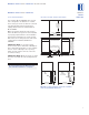
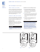
M O D E L S I C B 4 2 4 A N D I C B 4 2 4 F S I N S TA L L AT I O N MODELS ICB424 A N D ICB424FS S I T E P R E P A R AT I O N I N S TA L L AT I O N S P E C I F I C AT I O N S The Sub-Zero Model ICB424FS wine storage unit is designed to be attractive in a stand alone setting. It can also be slid into surrounding cabinetry with clearance dimensions slightly different than the standard built-in Model ICB424.
M O D E L S I C B 4 2 4 A N D I C B 4 2 4 F S I N S TA L L AT I O N MODELS ICB424 ICB424FS ELECTRICAL R E Q U I R E M E N T S U N PAC K I N G A N D M OV I N G A 220-240 V AC, 50/60 Hz, 10 amp circuit breaker and electrical supply are required. A separate circuit, servicing only this appliance, is required. Uncrate the unit, remove its wood base and discard the shipping bolts that hold the wood base to the bottom of the unit. Remove all packing materials and tape.
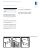
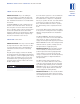
M O D E L S I C B 4 2 4 A N D I C B 4 2 4 F S I N S TA L L AT I O N A N T I - T I P B R AC K E T I N S TA L L AT I O N MODEL ICB424FS To prevent the unit from tipping forward and provide a stable installation, the unit must be secured in place with the anti-tip bracket. An anti-tip bracket and hardware is provided with the Wine Storage unit. The anti-tip bracket must be installed on a solid base to prevent tipover in case several loaded wine shelves are extended at the same time.
M O D E L S I C B 4 2 4 A N D I C B 4 2 4 F S I N S TA L L AT I O N MODELS ICB424 ICB424FS A N T I - T I P B R AC K E T I N S TA L L AT I O N W O O D F L O O R A P P L I C AT I O N S Installation for Concrete Wedge Anchors: Use the four #12 x 64 mm wood screws and the four 6 mm flat washers provided. Drill pilot holes 5 mm diameter maximum, and be sure that the screws penetrate through the flooring material and into the wall plate a minimum of 19 mm. Be sure that the screws hold tight.
M O D E L S I C B 4 2 4 A N D I C B 4 2 4 F S I N S TA L L AT I O N L O C K I N S TA L L AT I O N IMPORTANT NOTE: If you are adding an accessory lock kit to your Wine Storage unit, it should be installed before you position the unit. Installation instructions are included with the lock kit. For Model ICB424, the lock is attached to the bottom of the metal door frame. The decorative door panel is not involved in the installation or operation of the lock.
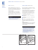
M O D E L S I C B 4 2 4 A N D I C B 4 2 4 F S I N S TA L L AT I O N MODELS ICB424 ICB424FS LEVEL T H E U N I T HOME ALARM C O N N E C T I O N S Using an adjustable wrench or pliers, turn each of the four leveling legs clockwise to raise the unit and counterclockwise to lower the unit. For the location of the leveling legs, see illustration 6 below. Before the kickplate is installed, all necessary wiring connections in the compressor compartment should be completed.
M O D E L S I C B 4 2 4 A N D I C B 4 2 4 F S I N S TA L L AT I O N K I C K P L AT E I N S TA L L AT I O N D O O R PA N E L S – M O D E L I C B 4 2 4 Once the unit is leveled and wiring connections made, the kickplate can be installed. Use the two #10 x 13 mm stainless steel screws that are provided with the kickplate. Refer to illustration 8 below. Model ICB424 is offered in two design applications; stainless steel (/S) and overlay (/O). Each of these designs are available as a glass door (G) model.
M O D E L S I C B 4 2 4 A N D I C B 4 2 4 F S I N S TA L L AT I O N MODELS ICB424 ICB424FS PA N E L DESIGN Additional panel design information can be found in the Sub-Zero Design Guide. Check our website at subzero.com. OV E R L AY D O O R P A N E L S OV E R L AY G L A S S D O O R – M O D E L I C B 4 2 4 Inspect the door panel for the minimum 16 mm thickness, the finished inside edge and the 5 kg weight limit. See the Wine Storage section of the Sub-Zero Design Guide for additional panel information.
M O D E L S I C B 4 2 4 A N D I C B 4 2 4 F S I N S TA L L AT I O N HINGE A D J U S T M E N T IMPORTANT NOTE: Install screws in all the mounting holes in the door frame. The nature of the door panel with a narrow outer rim and no connecting center member requires the support provided by the glass door. After the door panel installation is complete, apply the cover patches or plugs provided over the holes on the inside surface of the door.
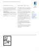
M O D E L S I C B 4 2 7 A N D I C B 4 2 7 R I N S TA L L AT I O N MODELS ICB427 ICB427R MODELS ICB427 A N D ICB427R I N S TA L L AT I O N S P E C I F I C AT I O N S Make sure that the finished rough opening where the Wine Storage unit is to be installed is properly prepared. Refer to the Installation Specifications illustration for rough opening dimensions, door swing clearance and electrical placement for Models ICB427 and ICB427R.
M O D E L S I C B 4 2 7 A N D I C B 4 2 7 R I N S TA L L AT I O N ELECTRICAL R E Q U I R E M E N T S U N PAC K I N G A N D M OV I N G A 220-240 V AC, 50/60 Hz, 10 amp circuit breaker and electrical supply are required. A separate circuit, servicing only this appliance, is required. Uncrate the unit, remove its wood base and discard the shipping bolts that hold the wood base to the bottom of the unit. Remove all packing materials and tape.
M O D E L S I C B 4 2 7 A N D I C B 4 2 7 R I N S TA L L AT I O N MODELS ICB427 ICB427R A N T I - T I P B R AC K E T I N S TA L L AT I O N W O O D F L O O R A P P L I C AT I O N S Use the six #12 x 64 mm wood screws and the six 6 mm flat washers provided. Drill pilot holes 5 mm diameter maximum, and be sure that the screws penetrate through the flooring material and into the wall plate a minimum of 19 mm. Be sure that the screws hold tight. Refer to illustration 1 below.
M O D E L S I C B 4 2 7 A N D I C B 4 2 7 R I N S TA L L AT I O N POSITION T H E U N I T Installation for Concrete Wedge Anchors: 1) Drill a 10 mm diameter hole any depth exceeding the minimum embedment. Clean the hole or continue drilling additional depth to accommodate drill fines. Use a carbide drill bit. Before moving the Wine Storage unit into position, secure the door closed. Remove the drawers of the Model ICB427R.
M O D E L S I C B 4 2 7 A N D I C B 4 2 7 R I N S TA L L AT I O N MODELS ICB427 ICB427R POSITION T H E U N I T IMPORTANT NOTE: If you are adding an accessory lock kit to your Model ICB427 or ICB427R, the catch should be installed at the top of appliance cabinet before you position the unit. See Lock Installation on page 23. Installation instructions are included with the lock kit. Remove the decorative top and side moldings and the kickplate / grille of the Wine Storage unit.
M O D E L S I C B 4 2 7 A N D I C B 4 2 7 R I N S TA L L AT I O N LEVEL T H E U N I T M O L D I N G I N S TA L L AT I O N Level the unit by turning the front leveling legs clockwise to raise the unit, or counterclockwise to lower it. To assist you in adjusting the front leveling legs up or down, use a standard screwdriver blade and place it in the front leveling leg as shown in illustration 4 below.
M O D E L S I C B 4 2 7 A N D I C B 4 2 7 R I N S TA L L AT I O N MODELS ICB427 ICB427R OPTIONAL COMPONENTS Optional installation components are available through your Sub-Zero dealer. You can also visit our website at subzero.com. OT H E R W I R I N G C O N N E C T I O N S Before the kickplate / grille is installed, all necessary wiring connections in the compressor compartment should be completed.
M O D E L S I C B 4 2 7 A N D I C B 4 2 7 R I N S TA L L AT I O N K I C K P L AT E / G R I L L E I N S TA L L AT I O N Once the unit is leveled and wiring connections made, the kickplate / grille can be installed. IMPORTANT NOTE: The kickplate / grille must be removed for servicing. The floor cannot interfere with removal. The louvered section of the kickplate / grille must not be covered so as to prevent air circulation.
M O D E L S I C B 4 2 7 A N D I C B 4 2 7 R I N S TA L L AT I O N MODELS ICB427 ICB427R PA N E L DESIGN Additional panel design information can be found in the Sub-Zero Design Guide. Check our website at subzero.com. S TA I N L E S S S T E E L D O O R P A N E L OV E R L AY G L A S S D O O R P A N E L Before installing the stainless steel door panel, check the panel carefully. Options are available for kickplate / grille height, overall height, door swing and door lock.
M O D E L S I C B 4 2 7 A N D I C B 4 2 7 R I N S TA L L AT I O N With the Wine Storage unit secured in position and the door closed, the panel is held in the desired position on the door and rapped by hand from the front, putting center marks on the rear surface of the panel. If the door panel is made of such a material that pre-drilling is needed, all of the mounting holes should be marked. If not, only enough holes to hold the panel in place temporarily, are necessary.
M O D E L S I C B 4 2 7 A N D I C B 4 2 7 R I N S TA L L AT I O N MODELS ICB427 ICB427R PA N E L DESIGN Additional panel design information can be found in the Sub-Zero Design Guide. Check our website at subzero.com. MODEL ICB427R D R AW E R PA N E L S With the two brackets in place on the drawer panel, engage the top dog-ear bracket first and then the lower bracket onto the protruding screws. You will have a 6 mm adjustment up and down and side to side in each drawer panel.
M O D E L S I C B 4 2 7 A N D I C B 4 2 7 R I N S TA L L AT I O N F I N I S H E D W O O D S I D E PA N E L S L O C K I N S TA L L AT I O N Side panels for Models ICB427 and ICB427R are not attached to the unit. You must securely fasten the panels to adjacent cabinets and floor. For Models ICB427 and ICB427R, the accessory lock is attached to the decorative door panel through a field-drilled hole in the panel.
M O D E L I C B 4 3 0 I N S TA L L AT I O N I N S T R U C T I O N S MODEL ICB430 M O D E L I C B 4 3 0 I N S TA L L AT I O N I N S TA L L AT I O N S P E C I F I C AT I O N S S I T E P R E P A R AT I O N Make sure that the finished rough opening where the Wine Storage unit is to be installed is properly prepared. Refer to the Installation Specifications illustration for rough opening dimensions, door swing clearance and electrical placement for Model ICB430.
M O D E L I C B 4 3 0 I N S TA L L AT I O N I N S T R U C T I O N S ELECTRICAL R E Q U I R E M E N T S U N PAC K I N G A N D M OV I N G A 220-240 V AC, 50/60 Hz, 10 amp circuit breaker and electrical supply are required. A separate circuit, servicing only this appliance, is required. Uncrate the unit, remove its wood base and discard the shipping bolts that hold the wood base to the bottom of the unit. Remove all packing materials and tape.
M O D E L I C B 4 3 0 I N S TA L L AT I O N I N S T R U C T I O N S MODEL ICB430 GRILLE R E M O VA L ANTI-TIP B L O C K I N G K I T In order to prevent damage to the grille and to access the power cord, the top grille assembly should be removed prior to moving the unit. Overlay panel grille: First, remove the inner grille panel assembly as shown in illustration 1 below. Lift up, then pull out at the bottom, pull the top section down and out of the top key slot.
M O D E L I C B 4 3 0 I N S TA L L AT I O N I N S T R U C T I O N S L O C K I N S TA L L AT I O N MODEL ICB430 IMPORTANT NOTE: If you are adding an accessory lock kit to your Wine Storage unit, it should be installed before you position the unit. Installation instructions are included with the lock kit. For Model ICB430, the lock is attached to the bottom of the metal door frame. The decorative door panel is not involved in the installation or operation of the lock.
M O D E L I C B 4 3 0 I N S TA L L AT I O N I N S T R U C T I O N S MODEL ICB430 HOME ALARM C O N N E C T I O N S Before the kickplate and grille are installed, all necessary wiring connections in the compressor compartment should be completed. If a home alarm system is to be installed on the Wine Storage unit, the connections should be made using the logic supplied with the alarm specifications.
M O D E L I C B 4 3 0 I N S TA L L AT I O N I N S T R U C T I O N S K I C K P L AT E A N D G R I L L E DOOR PA N E L S After the unit has been leveled, make sure the drain pan is installed properly and install the kickplate. Refer to illustration 7 below. Model ICB430 is offered in two design applications; stainless steel (/S) and overlay (/O). Each of these designs is available as a glass door (G) model. IMPORTANT NOTE: The kickplate must be removed for servicing.
M O D E L I C B 4 3 0 I N S TA L L AT I O N I N S T R U C T I O N S MODEL ICB430 PA N E L DESIGN Additional panel design information can be found in the Sub-Zero Design Guide. Check our website at subzero.com. OV E R L AY D O O R P A N E L If your customer has chosen an overlay design door and grille panel, the unit will be shipped without handle and hardware. The cabinet manufacturer or designer will provide handle hardware at the job site to match the overall decorating scheme.
M O D E L I C B 4 3 0 I N S TA L L AT I O N I N S T R U C T I O N S OV E R L AY G R I L L E P A N E L IMPORTANT NOTE: The size of the overlay panel is critical. It must fit over the door frame. To install overlay panels, first remove the magnet backed trim molding using a piece of tape to pull it away from the frame and expose the frame screws. The molding will bend at the center so that you can remove it. Remove the frame by removing the five screws holding it in place.
M O D E L I C B 4 3 0 I N S TA L L AT I O N I N S T R U C T I O N S MODEL ICB430 S I D E PA N E L I N S TA L L AT I O N If you’re installing a Model ICB430 with side panels, check with your installer or use one of the following Side Panel Installation Options. Drill three holes equidistant in a vertical section of the aluminum frame, and install pan head screws. Do not drill through model and serial number plate. Anchor the side panel with decorative screws or finishing nails from a local hardware store.
M O D E L I C B 4 3 0 I N S TA L L AT I O N I N S T R U C T I O N S ANCHOR T H E U N I T MODEL ICB430 After door and side panels have been installed, the unit has been leveled and door adjustment completed, anchor the unit to the opening. This will assure a proper fit and a secure installation. The Sub-Zero Anchoring Kit (part #4200900), available from your Sub-Zero dealer, includes the necessary hardware. IMPORTANT NOTE: Be sure to level and square the unit before anchoring it.
M O D E L I C B 4 3 0 I N S TA L L AT I O N I N S T R U C T I O N S MODEL ICB430 OPTIONAL COMPONENTS Optional installation components are available through your Sub-Zero dealer. You can also visit our website at subzero.com. HINGE A D J U S T M E N T I N S TA L L AT I O N C H E C K L I S T IMPORTANT NOTE: The unit must be installed and leveled before adjusting the door hinges. The importance of the installation of the Sub-Zero Wine Storage unit cannot be overemphasized.
S E RV I C E I N F O R M AT I O N S E RV I C E I N F O R M AT I O N I N S TA L L AT I O N C H E C K L I S T Has the packing material been removed? Turn the unit on first, is the unit operating properly? If not, is it plugged in? Is the control turned on? Has the unit been secured in place with an anti-tip bracket or by a secure overhead cabinet or structure? Are front leveling legs extended and making contact with the floor? Is the unit level? Is power cord connected directly to a properly grounded outlet
C O N S E R VA D O R E S D E V I N O D E S U B - Z E RO Debe tenerse en cuenta la importancia de la instalación de los conservadores de vino de Sub-Zero. Sólo un instalador cualificado debe realizar la instalación.
I N S TA L A C I Ó N D E L O S M O D E LO S I C B 4 2 4 E I C B 4 2 4 F S M O D E LO S I C B 4 2 4 E I C B 4 2 4 F S MODELOS P R E PA R A C I Ó N D E L S I T I O ICB424FS ICB424 E S P E C I F I C A C I O N E S D E L A I N S TA L A C I Ó N El conservador de vino de Sub-Zero, modelo ICB424FS, está diseñado para que resulte atractivo en una colocación independiente.
I N S TA L A C I Ó N D E L O S M O D E LO S I C B 4 2 4 E I C B 4 2 4 F S MODELOS R E Q U I S I TO S ELÉCTRICOS D E S E M B A L A J E Y D E S P L A Z A M I E N TO Es necesario que la red eléctrica y el cortacircuitos sean de 220-240 V CA, 50/60 hercios y 10 amperios. Se necesita un circuito separado que alimente solamente a esta unidad. Desembale la unidad, quite la base de madera y deseche los tornillos que sujetan esta base a la parte inferior de la unidad para el transporte.
I N S TA L A C I Ó N D E L O S M O D E LO S I C B 4 2 4 E I C B 4 2 4 F S I N S TA L A C I Ó N D E L S O P O R T E A N T I V U E LC O MODELOS ICB424 MODELO ICB424FS Para impedir que la unidad se incline hacia adelante y conseguir que su colocación sea estable, es necesario sujetar la unidad con el soporte anti-vuelco. El conservador de vino dispone de un soporte anti-vuelco y de las piezas de montaje correspondientes.
I N S TA L A C I Ó N D E L O S M O D E LO S I C B 4 2 4 E I C B 4 2 4 F S MODELOS ICB424 I N S TA L A C I Ó N D E L S O P O R T E A N T I V U E LC O ICB424FS Instalación de los anclajes de expansión para hormigón: APLIC ACIONES EN SUELO DE MADERA Utilice los cuatro tornillos para madera de 12 x 64 mm y las cuatro arandelas planas de 6 mm que se incluyen.
I N S TA L A C I Ó N D E L O S M O D E LO S I C B 4 2 4 E I C B 4 2 4 F S I N S TA L A C I Ó N D E L A C E R R A D U R A MODELOS ICB424 NOTA IMPORTANTE: Si va a agregar un sistema de cerradura como accesorio en el conservador de vino, éste debe instalarse antes de colocar el aparato en su sitio. Las instrucciones de instalación vienen incluidas con el sistema de cerradura. Para el modelo ICB424, la cerradura se fija en la parte inferior del marco metálico de la puerta.
I N S TA L A C I Ó N D E L O S M O D E LO S I C B 4 2 4 E I C B 4 2 4 F S MODELOS NIVELACIÓN D E L A U N I DA D C O N E X I O N E S D E ALARMA DOMÉSTICA Utilice una llave inglesa o unos alicates para girar cada una de las cuatro patas de nivelación en el sentido de las agujas del reloj para levantar el aparato y gírelas en sentido contrario para bajarlo. Para conocer dónde se encuentran las patas de nivelación, vea la ilustración 6 a continuación.
I N S TA L A C I Ó N D E L O S M O D E LO S I C B 4 2 4 E I C B 4 2 4 F S I N S TA L A C I Ó N D E L Z Ó C A LO PA N E L E S D E P U E R TA – M O D E L O ICB424 MODELOS ICB424 ICB424FS Cuando el aparato esté nivelado y las conexiones eléctricas realizadas, es le momento de colocar el zócalo. Utilice los dos tornillos para acero inoxidable de 10 x 13 mm que se incluyen con el zócalo. Vea la ilustración 8 a continuación.
I N S TA L A C I Ó N D E L O S M O D E LO S I C B 4 2 4 E I C B 4 2 4 F S MODELOS P A N E L E S D E P U E R TA R E V E S T I B L E ICB424 ICB424FS DISEÑO D E L PA N E L En la guía de diseño de Sub-Zero encontrará información adicional sobre el diseño de los paneles. Visite nuestra página Web, www.subzero.eu.com.
I N S TA L A C I Ó N D E L O S M O D E LO S I C B 4 2 4 E I C B 4 2 4 F S A J U S T E D E L A BISAGRA MODELOS ICB424 NOTA IMPORTANTE: Inserte los tornillos en todos los agujeros de montaje en el marco de la puerta. Las características del panel de la puerta con borde exterior estrecho y sin ningún miembro de centro de conexión hacen que sea necesario el soporte que proporciona la puerta de cristal.
I N S TA L A C I Ó N D E L O S M O D E LO S I C B 4 2 7 E I C B 4 2 7 R MODELOS M O D E LO S I C B 4 2 7 E I C B 4 2 7 R ICB427 ICB427R E S P E C I F I C A C I O N E S D E L A I N S TA L A C I Ó N P R E PA R A C I Ó N D E L S I T I O Compruebe que la cavidad en la que se va a instalar el conservador de vino está preparada correctamente.
I N S TA L A C I Ó N D E L O S M O D E LO S I C B 4 2 7 E I C B 4 2 7 R R E Q U I S I TO S ELÉCTRICOS D E S E M B A L A J E Y D E S P L A Z A M I E N TO MODELOS ICB427 Es necesario que la red eléctrica y el cortacircuitos sean de 220-240 V CA, 50/60 hercios y 10 amperios. Se necesita un circuito separado que alimente solamente a esta unidad. El cable eléctrico tiene conexión a tierra y se debe enchufar en un enchufe de pared de igual tipo con toma a tierra.
I N S TA L A C I Ó N D E L O S M O D E LO S I C B 4 2 7 E I C B 4 2 7 R MODELOS ICB427 I N S TA L A C I Ó N D E L S O P O R T E A N T I V U E LC O ICB427R APLIC ACIONES EN SUELO DE MADERA Utilice los seis tornillos para madera de 12 x 64 mm y las seis arandelas planas de 6 mm que se incluyen. Taladre agujeros guía con un diámetro máximo de 5 mm y asegúrese de que los tornillos penetran en el material del suelo y en la placa de la pared un mínimo de 19 mm. Procure que los tornillos queden bien apretados.
I N S TA L A C I Ó N D E L O S M O D E LO S I C B 4 2 7 E ICB427R C O LO C A C I Ó N D E L A U N I D A D MODELOS ICB427 ICB427R Instalación de los anclajes de expansión para hormigón: 1) Taladre un agujero de 10 mm de diámetro con una profundidad superior al incrustado mínimo. Limpie el agujero o continúe taladrando para hacer el agujero más profundo y que quepan los residuos en él. Utilice una broca de carburo.
I N S TA L A C I Ó N D E L O S M O D E LO S I C B 4 2 7 E I C B 4 2 7 R MODELOS C O LO C A C I Ó N D E L A U N I D A D ICB427 ICB427R NOTA IMPORTANTE: Si va a agregar un sistema de cerradura como accesorio en el modelo ICB427 o ICB427R, el dispositivo de cierre debe instalarse en la parte superior del armario del aparato antes de colocar éste en su sitio. Consulte la sección Instalación de cerradura en la página 57. Las instrucciones para su instalación se incluyen con el sistema de cerradura.
I N S TA L A C I Ó N D E L O S M O D E LO S I C B 4 2 7 E I C B 4 2 7 R NIVELACIÓN D E L A U N I DA D I N S TA L A C I Ó N D E L A M O L D U R A MODELOS ICB427 Nivele la unidad con las patas de nivelación: si se giran en el sentido de las agujas del reloj, se levanta la unidad, si se giran en el sentido contrario se baja la unidad.
I N S TA L A C I Ó N D E L O S M O D E LO S I C B 4 2 7 E I C B 4 2 7 R MODELOS OT R A S C O N E X I O N E S E L É C T R I C A S ICB427 ICB427R COMPONENTES OPCIONALES Existen componentes opcionales de instalación a su disposición a través del distribuidor de Sub-Zero. También puede visitar nuestra página Web www.subzero.eu.com. Antes de colocar el zócalo/ rejilla, es necesario realizar todas las conexiones de cableado necesarias en el compartimento del compresor.
I N S TA L A C I Ó N D E L O S M O D E LO S I C B 4 2 7 E I C B 4 2 7 R I N S TA L A C I Ó N D E L Z Ó C A LO / R E J I L L A MODELOS ICB427 Cuando el aparato esté nivelado y las conexiones eléctricas realizadas, es el momento de colocar el zócalo/ rejilla. NOTA IMPORTANTE: El zócalo/ rejilla debe ser extraíble para permitir sacarlo en caso de avería. El suelo no puede ser un impedimento para llevar a cabo esta operación.
I N S TA L A C I Ó N D E L O S M O D E LO S I C B 4 2 7 E I C B 4 2 7 R MODELOS ICB427 P A N E L D E L A P U E R TA D E A C E R O I N OX I DA B L E P A N E L D E P U E R TA D E C R I S TA L REVESTIBLE Antes de instalar el panel de la puerta de acero inoxidable, revíselo con cuidado. Hay distintas opciones disponibles para la altura del zócalo/ rejilla, la altura total, la apertura de la puerta y la cerradura de la puerta.
I N S TA L A C I Ó N D E L O S M O D E LO S I C B 4 2 7 E I C B 4 2 7 R MODELOS ICB427 Una vez que el conservador de vino se encuentra bien colocado y la puerta está cerrada, se sujeta el panel en la posición deseada sobre la puerta y se golpea con la mano desde la parte delantera de modo que las marcas de centro se indican en la superficie trasera del panel. Si el material del panel de la puerta exige taladrar los agujeros previamente, será necesario marcar todos los agujeros de montaje.
I N S TA L A C I Ó N D E L O S M O D E LO S I C B 4 2 7 E I C B 4 2 7 R MODELOS ICB427 P A N E L E S D E C A J O N E S D E L M O D E LO ICB427R ICB427R NOTA IMPORTANTE: Los paneles de los cajones del modelo ICB427R deben tener un grosor mínimo de 16 mm y ninguno puede superar los 5 kg de peso. DISEÑO D E L PA N E L En la guía de diseño de Sub-Zero encontrará información adicional sobre el diseño de los paneles. Visite nuestra página Web, www.subzero.eu.com.
I N S TA L A C I Ó N D E M O D E LO S I C B 4 2 7 E I C B 4 2 7 R PA N E L E S L AT E R A L E S D E M A D E R A AC A B A DA I N S TA L A C I Ó N D E L A C E R R A D U R A MODELOS ICB427 ICB427R Los paneles laterales de los modelos ICB427 e ICB427R no vienen acoplados. Debe sujetarlos de manera segura a los muebles contiguos y al suelo. Para ello, se deben utilizar soportes en “L” (piezas no incluidas).
I N S T R U C C I O N E S D E I N S TA L A C I Ó N D E L M O D E LO I C B 4 3 0 MODELO ICB430 I N S T R U C C I O N E S D E I N S TA L A C I Ó N D E L M O D E LO I C B 4 3 0 E S P E C I F I C A C I O N E S D E L A I N S TA L A C I Ó N Compruebe que la cavidad en la que se va a instalar el conservador de vino está preparada correctamente.
I N S T R U C C I O N E S D E I N S TA L A C I Ó N D E L M O D E LO I C B 4 3 0 R E Q U I S I TO S ELÉCTRICOS D E S E M B A L A J E Y D E S P L A Z A M I E N TO MODELO ICB430 Es necesario que la red eléctrica y el cortacircuitos sean de 220-240 V CA, 50/60 hercios y 10 amperios. Se necesita un circuito separado que alimente solamente a esta unidad. El cable eléctrico tiene conexión a tierra y se debe enchufar en un enchufe de pared de igual tipo con toma a tierra.
I N S T R U C C I O N E S D E I N S TA L A C I Ó N D E L M O D E LO I C B 4 3 0 MODELO E X T R AC C I Ó N D E L A REJILLA S O P O R T E D E B L O Q U E O A N T I - V U E LC O ICB430 Para evitar que se produzcan daños en la rejilla superior y para poder acceder al cable de conexión eléctrica, la rejilla superior debe retirarse antes de mover la unidad. Rejilla de panel revestible: retire en primer lugar el panel interior de rejilla, como se muestra en la ilustración 1 más abajo.
I N S T R U C C I O N E S D E I N S TA L A C I Ó N D E L M O D E LO I C B 4 3 0 I N S TA L A C I Ó N D E L A C E R R A D U R A MODELO ICB430 NOTA IMPORTANTE: Si va a agregar un sistema de cerradura como accesorio en el conservador de vino, éste debe instalarse antes de colocar el aparato en su sitio. Las instrucciones de instalación vienen incluidas con el sistema de cerradura. Para el modelo ICB430, la cerradura se fija en la parte inferior del marco metálico de la puerta.
I N S T R U C C I O N E S D E I N S TA L A C I Ó N D E L M O D E LO I C B 4 3 0 MODELO ICB430 C O N E X I O N E S D E ALARMA DOMÉSTICA Antes de colocar el zócalo y la rejilla, es necesario realizar todas las conexiones de cableado necesarias en el compartimento del compresor. Si se va a instalar un sistema de alarma doméstica en el conservador de vino, las conexiones deben realizarse según la lógica facilitada con las especificaciones de la alarma.
I N S T R U C C I O N E S D E I N S TA L A C I Ó N D E L M O D E LO I C B 4 3 0 Z Ó C A LO Y R E J I L L A P A N E L E S D E P U E R TA MODELO ICB430 Una vez que se ha nivelado la unidad, asegúrese de que el depósito de desagüe está instalado correctamente y coloque el zócalo. Vea la ilustración 7 a continuación. El modelo ICB430 se distribuye con dos opciones de diseño: acero inoxidable (/S) y revestible (/O). Cada uno de estos diseños está disponible, a su vez, como modelo con puerta de cristal (G).
I N S T R U C C I O N E S D E I N S TA L A C I Ó N D E L M O D E LO I C B 4 3 0 MODELO P A N E L D E P U E R TA R E V E S T I B L E ICB430 DISEÑO D E L PA N E L En la guía de diseño de Sub-Zero encontrará información adicional sobre el diseño de los paneles. Visite nuestra página Web, www.subzero.eu.com. Si el cliente ha elegido una puerta revestible y un panel de rejilla, la unidad se enviará sin el tirador ni las piezas de montaje de éste.
I N S T R U C C I O N E S D E I N S TA L A C I Ó N D E L M O D E LO I C B 4 3 0 R E J I L L A D E L PA N E L R E V E S T I B L E MODELO ICB430 NOTA IMPORTANTE: El tamaño del panel revestible es fundamental, ya que debe quedar ajustado en el marco de la puerta. Para instalar paneles revestibles, retire primero la moldura del borde magnético con una pieza de cinta para sacarla del marco y que se vean los tornillos del marco. La moldura se doblará por el centro para que pueda retirarla.
I N S T R U C C I O N E S D E I N S TA L A C I Ó N D E L M O D E LO I C B 4 3 0 MODELO I N S TA L A C I Ó N D E L PA N E L L AT E R A L ICB430 Si va a instalar un modelo ICB430 con paneles laterales, consulte al instalador o utilice una de las siguientes opciones de instalación de paneles laterales. Taladre tres agujeros equidistantes en una sección vertical del marco de aluminio e inserte tornillos de cabeza plana. No taladre agujeros en la placa donde constan el modelo y el número de serie.
I N S T R U C C I O N E S D E I N S TA L A C I Ó N D E L M O D E LO I C B 4 3 0 ANCLAJE D E L A U N I DA D MODELO ICB430 Una vez que la puerta y los paneles laterales están instalados, la unidad se ha nivelado y se ha ajustado la puerta, ancle la unidad a la cavidad. De este modo, se garantiza un ajuste adecuado y una colocación segura. El equipo de anclaje de Sub-Zero (pieza nº 4200900), que le puede facilitar su distribuidor de Sub-Zero, incluye todas las piezas necesarias para el montaje.
I N S T R U C C I O N E S D E I N S TA L A C I Ó N D E L M O D E LO I C B 4 3 0 MODELO A J U S T E D E L A BISAGRA L I S TA D E C O M P R O B A C I Ó N D E L A I N S TA L A C I Ó N NOTA IMPORTANTE: La unidad debe estar instalada y nivelada antes de que se ajusten las bisagras de la puerta. Debe tenerse en cuenta la importancia de la instalación de los conservadores de vino de Sub-Zero. Llevar a cabo una instalación correcta es responsabilidad del instalador o del distribuidor de ventas.
I N F O R M A C I Ó N S O B R E E L M A N T E N I M I E N TO I N F O R M AC I Ó N S O B R E E L MANTENIM I E N TO L I S TA D E C O M P R O B A C I Ó N D E L A I N S TA L A C I Ó N ¿Ha retirado el material de embalaje? Encienda el aparato por primera vez, ¿funciona correctamente? Si no es así, compruebe si el aparato está enchufado.
C AV E S A V I N S U B - Z E R O On ne soulignera jamais assez l’importance que revêt l’installation d’une cave à vin Sub-Zero, qui devrait être confiée à un poseur qualifié.
I N S TA L L AT I O N D E S M O D E L E S I C B 4 2 4 E T I C B 4 2 4 F S DES MODELES ICB424 E T ICB424FS MODELES ICB424 P R E P A R AT I O N D E L ’ E M P L A C E M E N T S P E C I F I C AT I O N S D ’ I N S TA L L AT I O N Le modèle de cave à vin ICB424FS Sub-Zero (posable) a été conçu pour pouvoir être posé dans les différents endroits de la maison.
I N S TA L L AT I O N D E S M O D E L E S I C B 4 2 4 E T I C B 4 2 4 F S MODELES C O N F I G U R AT I O N E L E C T R I Q U E DEBALLAGE E T DEPLACEMENT DE L’ A P PA R E I L Vous aurez besoin d’une alimentation électrique de 220 - 240 V c.a., 50/60 Hz et d’un disjoncteur de 10 A. Un circuit séparé, alimentant uniquement cet appareil ménager, est également requis. Dégagez l’appareil, enlevez le socle en bois et jetez les écrous qui retiennent le socle à la base de l’appareil.
I N S TA L L AT I O N D E S M O D E L E S I C B 4 2 4 E T I C B 4 2 4 F S I N S TA L L AT I O N D U S U P P O R T ANTIBASCULEMENT MODELES ICB424 MODELE ICB424FS Pour éviter que l’appareil ne bascule vers l’avant et assurer la stabilité de l’installation, il doit être maintenu en place à l’aide du support antibasculement. Un support antibasculement et des accessoires de quincaillerie sont fournis avec la cave à vin.
I N S TA L L AT I O N D E S M O D E L E S I C B 4 2 4 E T I C B 4 2 4 F S MODELES ICB424 I N S TA L L AT I O N D U S U P P O R T ANTIBASCULEMENT ICB424FS Installation des ancrages à cale pour sol en béton : SUR UN PLANCHER DE BOIS Utilisez les quatre vis à bois n° 12 x 64 mm et les quatre rondelles plates de 6 mm fournies.
I N S TA L L AT I O N D E S M O D E L E S I C B 4 2 4 E T I C B 4 2 4 F S I N S TA L L AT I O N D U S Y S T E M E D E VERROUILLAGE MODELES ICB424 ICB424FS REMARQUE IMPORTANTE : Si vous ajoutez un système de verrouillage à votre cave à vin, vous devriez l’installer avant d’insérer l’appareil à sa place. Les instructions d’installation sont fournies avec le système de verrouillage. Pour le modèle ICB424, le système de verrouillage est fixé à la base du cadre de porte en métal.
I N S TA L L AT I O N D E S M O D E L E S I C B 4 2 4 E T I C B 4 2 4 F S MODELES MISE A NIVEAU D E L’ A P PA R E I L C O N N E X I O N AU SYSTEME D’ALARME DE LA MAISON A l’aide d’une clé ajustable ou de pinces, tournez chacun des quatre pieds de mise à niveau dans le sens des aiguilles d’une montre pour remonter l’appareil ou dans le sens contraire pour l’abaisser. Pour repérer l’emplacement des pieds de mise à niveau, reportez-vous à la figure 6 ci-après.
I N S TA L L AT I O N D E S M O D E L E S I C B 4 2 4 E T I C B 4 2 4 F S I N S TA L L AT I O N D E L A P L I N T H E PA N N E A U X D E P O R T E – M O D E L E ICB424 MODELES ICB424 ICB424FS Une fois que l’appareil est de niveau et que les branchements ont été effectués, vous pouvez installer la plinthe à l’aide des deux vis n° 10 x 13 mm en acier inoxydable fournies. Reportezvous à la figure 8 ci-après. REMARQUE IMPORTANTE : La plinthe doit être retirée en cas de réparation.
I N S TA L L AT I O N D E S M O D E L E S I C B 4 2 4 E T I C B 4 2 4 F S MODELES PA N N E A U X D E P O RT E H A B I L LA B L E S ICB424 ICB424FS MODELES D E PA N N E A U X D’autres informations sur les modèles de panneaux sont fournies dans le Guide de design Sub-Zero. Consultez notre site Internet, subzero.com.
I N S TA L L AT I O N D E S M O D E L E S I C B 4 2 4 E T I C B 4 2 4 F S AJUSTEMENT DES CHARNIERES MODELES ICB424 REMARQUE IMPORTANTE : Insérez les vis dans les trous de montage du cadre de porte. Comme le panneau de porte est doté d’une moulure extérieure étroite et n’est pourvu d’aucun dispositif de fixation au centre, il nécessite le support que lui fournit la porte vitrée.
I N S TA L L AT I O N D E S M O D E L E S I C B 4 2 7 E T I C B 4 2 7 R MODELES MODELES ICB427 E T ICB427R ICB427 ICB427R S P E C I F I C AT I O N S D ’ I N S TA L L AT I O N Assurez-vous que l’ouverture dans laquelle la cave à vin sera installée est correctement préparée et finie. Reportez-vous à la figure Spécifications d’installation des modèles ICB427 et ICB427R pour consulter les dimensions de l'ouverture et du dégagement de la porte et repérer l’emplacement des branchements électriques.
I N S TA L L AT I O N D E S M O D E L E S I C B 4 2 7 E T I C B 4 2 7 R C O N F I G U R AT I O N E L E C T R I Q U E DEBALLAGE E T DEPLACEMENT DE L’ A P PA R E I L MODELES ICB427 ICB427R Vous aurez besoin d’une alimentation électrique de 220 - 240 V c.a., 50/60 Hz et d’un disjoncteur de 10 A. Un circuit séparé, alimentant uniquement cet appareil ménager, est également requis. Dégagez l’appareil, enlevez le socle en bois et jetez les écrous qui retiennent le socle à la base de l’appareil.
I N S TA L L AT I O N D E S M O D E L E S I C B 4 2 7 E T I C B 4 2 7 R MODELES ICB427 I N S TA L L AT I O N D U S U P P O R T ANTIBASCULEMENT ICB427R SUR UN PLANCHER DE BOIS Pour éviter que l’appareil ne bascule vers l’avant et assurer la stabilité de l’installation, installez le support antibasculement et déployez les pieds de mise à niveau jusqu’au sol. Un support antibasculement et des accessoires de quincaillerie sont fournis avec la cave à vin.
I N S TA L L AT I O N D E S M O D E L E S I C B 4 2 7 E T I C B 4 2 7 R MISE EN PLACE D E L’ A P PA R E I L MODELES ICB427 ICB427R Installation des ancrages à cale pour sol en béton : 1) Percez un trou de 10 mm de diamètre à une profondeur excédant l’enfouissement minimum. Nettoyez le trou ou continuez à percer plus profond afin d’enfoncer les mèches fines. Utilisez une mèche à pointe de carbure.
I N S TA L L AT I O N D E S M O D E L E S I C B 4 2 7 E T I C B 4 2 7 R MODELES MISE EN PLACE D E L’ A P PA R E I L ICB427 ICB427R REMARQUE IMPORTANTE : Si vous ajoutez un système de verrouillage à votre modèle ICB427 ou ICB427R, vous devriez installer le taquet sur le dessus de l’élément contenant l’appareil avant de mettre ce dernier à son emplacement définitif. Reportez-vous à la section Installation du système de verrouillage page 91.
I N S TA L L AT I O N D E S M O D E L E S I C B 4 2 7 E T I C B 4 2 7 R MISE A NIVEAU D E L’ A P PA R E I L P O S E D E L A M O U LU R E MODELES ICB427 Mettez l’appareil de niveau en tournant les pieds de mise à niveau dans le sens des aiguilles d’une montre pour le remonter ou dans le sens contraire pour l’abaisser.
I N S TA L L AT I O N D E S M O D E L E S I C B 4 2 7 E T I C B 4 2 7 R MODELES AUTRES B R A N C H E M E N T S ICB427 ICB427R COMPOSANTS OPTIONNELS Vous pouvez vous procurer les composants optionnels auprès de votre revendeur Sub-Zero. Vous pouvez aussi consulter notre site Internet, subzero.com. Tous les branchements de fils qui doivent être effectués dans le compresseur devraient être terminés avant l’installation de la plinthe/grille.
I N S TA L L AT I O N D E S M O D E L E S I C B 4 2 7 E T I C B 4 2 7 R I N S TA L L AT I O N D E L A P L I N T H E / GRILLE MODELES ICB427 ICB427R Une fois que l’appareil est de niveau et que les branchements ont été effectués, vous pouvez installer la plinthe/grille. REMARQUE IMPORTANTE : La plinthe/ grille doit être retirée en cas de réparation. Le sol ne doit pas gêner le retrait. La section à persiennes de la plinthe/grille ne doit pas être recouverte car l’air ne pourrait pas circuler.
I N S TA L L AT I O N D E S M O D E L E S I C B 4 2 7 E T I C B 4 2 7 R MODELES ICB427 PA N N E A U D E P O RT E E N AC I E R I N OX Y DA B L E PA N N E A U D E P O RT E V I T R E E HABILLABLE Avant d’installer le panneau de porte en acier inoxydable, vérifiez-le attentivement. Plusieurs options sont disponibles pour la hauteur de la plinthe/grille, la hauteur hors tout, l’ouverture de porte et le verrouillage de porte.
I N S TA L L AT I O N D E S M O D E L E S I C B 4 2 7 E T I C B 4 2 7 R MODELES ICB427 ICB427R Maintenez la cave à vin en place avec la porte fermée et positionnez le panneau à l’emplacement souhaité sur la porte en frappant de la main d’un coup sur le devant de façon à marquer les repères centraux sur sa face arrière. Si le panneau de porte est fabriqué d’un matériau qui nécessite de percer des avant-trous, tous les trous de montage devraient être marqués.
I N S TA L L AT I O N D E S M O D E L E S I C B 4 2 7 E T I C B 4 2 7 R MODELES ICB427 PA N N E A U X D E T I RO I R D U M O D E L E ICB427R ICB427R Tandis que les deux supports sont en place sur le panneau de tiroir, engagez d’abord le support à pattes supérieur, puis le support inférieur sur les vis qui sortent du tiroir. Vous pourrez ajuster le panneau de tiroir de 6 mm vers le haut, vers le bas ou sur les côtés. Serrez toutes les vis sur le support inférieur pour fixer le panneau de tiroir.
I N S TA L L AT I O N D E S M O D E L E S I C B 4 2 7 E T I C B 4 2 7 R PA N N E A U X L AT E R A U X E N B O I S FINIS I N S TA L L AT I O N D U S Y S T E M E D E VERROUILLAGE MODELES ICB427 ICB427R Les panneaux latéraux des modèles ICB427 et ICB427R ne sont pas attachés à l’appareil. Vous devez solidement les fixer aux éléments et au sol adjacents. Pour ce faire, vous devriez utiliser des supports en « L » (les accessoires de quincaillerie ne sont pas fournis).
I N S T R U C T I O N S D ’ I N S TA L L AT I O N D U M O D E L E I C B 4 3 0 MODELE I N S TA L L AT I O N D U M O D E L E I C B 4 3 0 ICB430 S P E C I F I C AT I O N S D ’ I N S TA L L AT I O N Assurez-vous que l’ouverture dans laquelle la cave à vin sera installée est correctement préparée et finie.
I N S T R U C T I O N S D ’ I N S TA L L AT I O N D U M O D E L E I C B 4 3 0 C O N F I G U R AT I O N E L E C T R I Q U E DEBALLAGE E T DEPLACEMENT DE L’ A P PA R E I L Vous aurez besoin d’une alimentation électrique de 220 - 240 V c.a., 50/60 Hz et d’un disjoncteur de 10 A. Un circuit séparé, alimentant uniquement cet appareil ménager, est également requis. Dégagez l’appareil, enlevez le socle en bois et jetez les écrous qui retiennent le socle à la base de l’appareil.
I N S T R U C T I O N S D ’ I N S TA L L AT I O N D U M O D E L E I C B 4 3 0 MODELE R E T R A I T D E L A GRILLE K I T D E B L O C AG E A N T I B A S C U L E M E N T ICB430 Afin d’éviter d’endommager la grille et de pouvoir accéder au cordon d’alimentation, vous ne devriez pas retirer la grille supérieure avant de déplacer l’appareil. Grille à panneau d’habillage : Tout d’abord, retirez le panneau de grille intérieur, tel qu’illustré à la figure 1 ci-après.
I N S T R U C T I O N S D ’ I N S TA L L AT I O N D U M O D E L E I C B 4 3 0 I N S TA L L AT I O N D U S Y S T E M E D E VERROUILLAGE REMARQUE IMPORTANTE : Si vous ajoutez un système de verrouillage à votre cave à vin, vous devriez l’installer avant de mettre l’appareil à son emplacement définitif. Les instructions d’installation sont fournies avec le système de verrouillage. Pour le modèle ICB430, le système de verrouillage est fixé à la base du cadre de porte en métal.
I N S T R U C T I O N S D ’ I N S TA L L AT I O N D U M O D E L E I C B 4 3 0 MODELE ICB430 C O N N E X I O N AU SYSTEME D’ALARME DE LA MAISON Tous les branchements de fils qui doivent être effectués dans le compresseur devraient être terminés avant l’installation de la plinthe et de la grille. S’il est prévu de connecter le système d’alarme de la maison à la cave à vin, les branchements devraient être effectués selon les instructions accompagnant les spécifications de l’alarme.
I N S T R U C T I O N S D ’ I N S TA L L AT I O N D U M O D E L E I C B 4 3 0 PLINTHE E T GRILLE PA N N E A U X D E P O R T E MODELE ICB430 Une fois que l’appareil a été mis de niveau, assurez-vous que le bac de vidange est installé correctement et posez la plinthe. Reportez-vous à la figure 7 ci-après. Le modèle ICB430 est offert dans deux versions : acier inoxydable (/S) et habillable (/O). Dans chacune de ces versions, le modèle peut être équipé d’une porte vitrée (G).
I N S T R U C T I O N S D ’ I N S TA L L AT I O N D U M O D E L E I C B 4 3 0 MODELE PA N N E A U D E P O RT E H A B I L LA B L E ICB430 MODELES D E PA N N E A U X D’autres informations sur les modèles de panneaux sont fournies dans le Guide de design Sub-Zero. Consultez notre site Internet, subzero.com. Si votre client a choisi une porte et un panneau de grille habillables, l’appareil sera expédié sans la poignée et les accessoires de quincaillerie.
I N S T R U C T I O N S D ’ I N S TA L L AT I O N D U M O D E L E I C B 4 3 0 PA N N E A U DE GRILLE HABILLABLE MODELE ICB430 REMARQUE IMPORTANTE : Les dimensions du panneau habillable sont cruciales. En effet, le panneau doit s’adapter sur le cadre de porte. Pour installer les panneaux habillables, enlevez d’abord la moulure à endos aimanté. Pour ce faire, utilisez un morceau de ruban adhésif pour la détacher du cadre et exposer les vis. La moulure pliera au centre et vous pourrez la retirer.
I N S T R U C T I O N S D ’ I N S TA L L AT I O N D U M O D E L E I C B 4 3 0 MODELE P O S E D E S PA N N E A U X L AT E R A U X ICB430 Si vous installez un modèle ICB430 avec des panneaux latéraux, adressez-vous à votre poseur ou procédez selon l’une des options de pose de panneaux latéraux suivantes. Percez trois trous équidistants dans la section verticale du cadre en aluminium et posez les vis à tête cylindrique bombée. Ne percez pas dans la plaque des numéros de modèle et de série.
I N S T R U C T I O N S D ’ I N S TA L L AT I O N D U M O D E L E I C B 4 3 0 ANCRAGE D E L’ A P PA R E I L MODELE ICB430 Après avoir posé la porte et les panneaux latéraux, mis à niveau l’appareil et ajusté la porte, ancrez l’appareil dans l’ouverture. Vous assurerez ainsi une installation sûre et bien ajustée. Le kit d’ancrage Sub-Zero (pièce n° 4200900), disponible chez votre revendeur Sub-Zero, comprend les accessoires de quincaillerie nécessaires.
I N S T R U C T I O N S D ’ I N S TA L L AT I O N D U M O D E L E I C B 4 3 0 MODELE A J U S T E M E N T DES CHARNIERES L I S T E D E C O N T RO L E D E L’ I N S TA L L AT I O N REMARQUE IMPORTANTE : Les ajustements des charnières de porte ne peuvent pas être effectués tant que l’appareil n’a pas été installé et mis à niveau. On ne soulignera jamais assez l’importance que revêt l’installation d’une cave à vin Sub-Zero.
SERVICE A P R E S - V E N T E SERVICE A P R E S - V E N T E L I S T E D E C O N T RO L E D E L ’ I N S TA L L AT I O N Le matériel d’emballage a-t-il été enlevé ? Mettez l’appareil sous tension ; est-ce qu’il fonctionne correctement ? Si ce n’est pas le cas, est-il branché ? Le bouton de commande est-il sur ON ? L’appareil a-t-il été fixé au moyen d’un support antibasculement ou d’un élément de cuisine ou autre structure en hauteur ? Tous les pieds de mise à niveau ont-ils été déployés et reposent-ils sur
CANTINA PER VINI S U B - Z E RO L’importanza di una corretta installazione della cantina per vini Sub-Zero non deve essere sottovalutata. L’installazione deve essere effettuata da personale qualificato.
I N S TA L L A Z I O N E D E I M O D E L L I I C B 4 2 4 E I C B 4 2 4 F S MODELLI ICB424 E ICB424FS MODELLI ICB424 P R E PA R A Z I O N E D E L S I TO ICB424FS S P E C I F I C H E P E R L ’ I N S TA L L A Z I O N E La cantina per vini Sub-Zero modello ICB424FS è progettata per essere elegante anche nella versione autonoma. L’unità può anche essere integrata nei mobili circostanti grazie a dimensioni leggermente diverse rispetto al modello ICB424 standard a incasso.
I N S TA L L A Z I O N E D E I M O D E L L I I C B 4 2 4 E I C B 4 2 4 F S MODELLI R E Q U I S I T I ELETTRICI D I S I M B A L L A G G I O E S P O S TA M E N TO È necessaria una presa di corrente da 220-240 V c.a., 50/60 Hz, 10 ampere, collegata a un interruttore automatico. Per questo elettrodomestico è necessario predisporre un circuito elettrico dedicato. Disimballare l’unità, rimuovere la base in legno e gettare i bulloni di spedizione che fissano la base in legno al fondo dell’unità.
I N S TA L L A Z I O N E D E I M O D E L L I I C B 4 2 4 E I C B 4 2 4 F S I N S TA L L A Z I O N E D E L L A B A R R A A N T I R I B A LTA M E N TO MODELLI ICB424 MODEL ICB424FS Per impedire che l’unità si ribalti in avanti e garantire un’installazione stabile, l’unità va fissata in posizione mediante la barra antiribaltamento. L’unità dispone di una barra antiribaltamento e di minuteria.
I N S TA L L A Z I O N E D E I M O D E L L I I C B 4 2 4 E I C B 4 2 4 F S MODELLI ICB424 I N S TA L L A Z I O N E D E L L A B A R R A A N T I R I B A LTA M E N TO ICB424FS Installazione dei tasselli per cemento: A P P L I C A Z I O N E P E R PAV I M E N T I IN LEGNO 1) Praticare un foro con diametro di 10 mm con profondità superiore all’incasso minimo. Pulire il foro o continuare a perforare più in profondità per depositare i residui. Usare una punta al carburo.
I N S TA L L A Z I O N E D E I M O D E L L I I C B 4 2 4 E I C B 4 2 4 F S I N S TA L L A Z I O N E D E L LU C C H E T TO MODELLI ICB424 NOTA IMPORTANTE: se si desidera aggiungere un lucchetto accessorio alla cantina per vini, questo dovrà essere installato prima di posizionare l’unità. Le istruzioni per l’installazione sono in dotazione con il lucchetto. Nel modello ICB424, il lucchetto viene montato sulla parte inferiore del telaio metallico della porta.
I N S TA L L A Z I O N E D E I M O D E L L I I C B 4 2 4 E I C B 4 2 4 F S MODELLI L I V E L L A M E N TO D E L L ’ U N I T À C O N N E S S I O N I D E L SISTEMA DI ALLARME DOMESTICO Servendosi di una chiave o pinza regolabili, ruotare ciascuno dei quattro piedini di livellamento in senso orario per sollevare l’unità, in senso antiorario per abbassarla. Per la posizione dei piedini di livellamento, consultare la Figura 6 di seguito.
I N S TA L L A Z I O N E D E I M O D E L L I I C B 4 2 4 E I C B 4 2 4 F S I N S TA L L A Z I O N E D E L L O Z O C C O LO PA N N E L L I P E R P O R TA – M O D E L L O ICB424 MODELLI ICB424 ICB424FS Una volta messa a livello l’unità ed eseguito il cablaggio, lo zoccolo è pronto per essere installato. Usare le due le viti in acciaio inossidabile da 10 x 13 mm in dotazione con lo zoccolo. Fare riferimento alla Figura 8 di seguito.
I N S TA L L A Z I O N E D E I M O D E L L I I C B 4 2 4 E I C B 4 2 4 F S MODELLI ICB424 P A N N E L L I P E R P O R TA A S O V R A P POSIZIONE ICB424FS PA N N E L L I A S OV R A P P O S I Z I O N E P E R P O RTA I N V E T RO – M O D E L L O I C B 4 2 4 DESIGN D E I PA N N E L L I Ulteriori informazioni sul design dei pannelli sono disponibili nella guida al design SubZero. Consultare il nostro sito Web all’indirizzo subzero.com.
I N S TA L L A Z I O N E D E I M O D E L L I I C B 4 2 4 E I C B 4 2 4 F S REGISTRAZIONE D E I C A R D I N I MODELLI ICB424 NOTA IMPORTANTE: installare le viti in tutti i fori di montaggio del telaio della porta. Il tipo di pannello con bordo esterno molto stretto e privo di elementi di connessione richiede il sostegno fornito dalla porta di vetro. Dopo aver completato l’installazione del pannello, applicare i tappi in dotazione per coprire i fori sulla superficie interna della porta.
I N S TA L L A Z I O N E D E I M O D E L L I I C B 4 2 7 E I C B 4 2 7 R MODELLI MODELLI ICB427 E ICB427R ICB427 ICB427R S P E C I F I C H E P E R L ’ I N S TA L L A Z I O N E Accertarsi che l’incasso finito in cui viene installata la cantina per vini sia preparato correttamente.
I N S TA L L A Z I O N E D E I M O D E L L I I C B 4 2 7 E I C B 4 2 7 R R E Q U I S I T I ELETTRICI D I S I M B A L L A G G I O E S P O S TA M E N TO MODELLI ICB427 È necessaria una presa di corrente da 220-240 V c.a., 50/60 Hz, 16 A collegata ad un interruttore automatico. Per questo elettrodomestico è necessario predisporre un circuito elettrico dedicato. Disimballare l’unità, rimuovere la base in legno e gettare i bulloni di spedizione che fissano la base in legno al fondo dell’unità.
I N S TA L L A Z I O N E D E I M O D E L L I I C B 4 2 7 E I C B 4 2 7 R MODELLI ICB427 I N S TA L L A Z I O N E D E L L A B A R R A A N T I R I B A LT A M E N T O ICB427R A P P L I C A Z I O N E P E R PAV I M E N T I I N LEGNO Per impedire che l’unità si ribalti in avanti e garantire un’installazione stabile, installare la barra antiribaltamento e allungare i piedini anteriori di livellamento sul pavimento. L’unità dispone di una barra antiribaltamento e di minuteria.
I N S TA L L A Z I O N E D E I M O D E L L I I C B 4 2 7 E I C B 4 2 7 R P O S I Z I O N A M E N TO D E L L ’ U N I T À MODELLI ICB427 ICB427R Installazione dei tasselli per cemento: 1) Praticare un foro con diametro di 10 mm con profondità superiore all’incasso minimo. Pulire il foro o continuare a perforare più in profondità per depositare i residui. Usare una punta al carburo. 2) Montare la rondella e il dado a filo con l’estremità del tassello per proteggere la filettatura.
I N S TA L L A Z I O N E D E I M O D E L L I I C B 4 2 7 E I C B 4 2 7 R MODELLI P O S I Z I O N A M E N TO D E L L ’ U N I T À ICB427 ICB427R NOTA IMPORTANTE: se si desidera aggiungere un lucchetto accessorio ai modelli ICB427 o ICB427R, il fermo dovrà essere montato sul lato superiore dell’elettrodomestico prima di posizionare l’unità. Consultare Installazione del lucchetto a pagina 125. Le istruzioni per l’installazione sono in dotazione con il kit del lucchetto.
I N S TA L L A Z I O N E D E I M O D E L L I I C B 4 2 7 E I C B 4 2 7 R L I V E L L A M E N TO D E L L ’ U N I T À Mettere a livello l’unità ruotando i piedini di livellamento in senso orario per sollevare l’unità o in senso antiorario per abbassarla. Per favorire la regolazione dei piedini di livellamento anteriori (in su o in giù), usare un cacciavite standard e posizionarlo nel piedino di livellamento anteriore, come mostrato nella Figura 4 di seguito.
I N S TA L L A Z I O N E D E I M O D E L L I I C B 4 2 7 E I C B 4 2 7 R MODELLI ICB427 A LT R E C O N N E S S I O N I D I C ABLAGGIO ICB427R Prima di installare lo zoccolo / la griglia, è necessario completare tutti i collegamenti di cablaggio all’interno del compressore. ACCESSORI OPZIONALI Sono disponibili accessori di installazione opzionali presso il proprio rivenditore SubZero di zona. È possibile anche visitare il nostro sito Web all’indirizzo subzero.com.
I N S TA L L A Z I O N E D E I M O D E L L I I C B 4 2 7 E I C B 4 2 7 R I N S TA L L A Z I O N E D E L L O Z O C C O LO / D E L L A GRIGLIA MODELLI ICB427 ICB427R Una volta messa a livello l’unità ed eseguito il cablaggio, lo zoccolo / la griglia può essere installato/a. NOTA IMPORTANTE: deve essere possibile rimuovere lo zoccolo/ la griglia per interventi di manutenzione. Il pavimento non deve interferire con la rimozione.
I N S TA L L A Z I O N E D E I M O D E L L I I C B 4 2 7 E I C B 4 2 7 R MODELLI ICB427 ICB427R DESIGN DEI PA N N E L L I Ulteriori informazioni sul design dei pannelli sono disponibili nella guida al design SubZero. Consultare il nostro sito Web all’indirizzo subzero.com.
I N S TA L L A Z I O N E D E I M O D E L L I I C B 4 2 7 E I C B 4 2 7 R MODELLI ICB427 Una volta fissata la cantina in posizione con le porte ben chiuse, mantenere il pannello nella posizione desiderata e battere con le mani la parte anteriore ponendo contrassegni di centratura sulla superficie posteriore del pannello. Se il pannello è fabbricato con materiali che hanno bisogno di essere preforati, tutti i fori di montaggio vanno contrassegnati.
I N S TA L L A Z I O N E D E I M O D E L L I I C B 4 2 7 E I C B 4 2 7 R MODELLI ICB427 PA N N E L L I P E R C A S S E T T I M O D E L ICB427R ICB427R NOTA IMPORTANTE: il pannello per cassetti del modello ICB427R deve avere uno spessore minimo di 16 mm e non deve superare i 5 kg per ciascun pannello. DESIGN DEI PA N N E L L I Togliere la minuteria di montaggio in dotazione e riporla di lato. Lavorare sul lato posteriore dei singoli pannelli e proteggere la parte anteriore.
I N S TA L L A Z I O N E D E I M O D E L L I I C B 4 2 7 E I C B 4 2 7 R PA N N E L L I L AT E R A L I R I F I N I T I I N LEGNO I N S TA L L A Z I O N E D E L L U C C H E T T O MODELLI ICB427 ICB427R I pannelli laterali per i modelli ICB427 e ICB427R non sono fissati all’unità. Fissare bene i pannelli ai pensili adiacenti ed al pavimento. I pannelli vanno fissati al pavimento e alle pareti utilizzando barre a L (minuteria non in dotazione).
I S T R U Z I O N I D I I N S TA L L A Z I O N E D E L M O D E L LO I C B 4 3 0 MODELLO I N S TA L L A Z I O N E M O D E L L O I C B 4 3 0 ICB430 S P E C I F I C H E P E R L ’ I N S TA L L A Z I O N E Accertarsi che l’incasso finito in cui viene installata la cantina per vini sia preparato correttamente.
I S T R U Z I O N I D I I N S TA L L A Z I O N E D E L M O D E L LO I C B 4 3 0 R E Q U I S I T I ELETTRICI D I S I M B A L L A G G I O E S P O S TA M E N TO MODELLO ICB430 È necessaria una presa di corrente da 220-240 V c.a., 50/60 Hz, 16 A, collegata ad un interruttore automatico. Per questo elettrodomestico è necessario predisporre un circuito elettrico dedicato. Disimballare l’unità, rimuovere la base in legno e gettare i bulloni di spedizione che fissano la base in legno al fondo dell’unità.
I S T R U Z I O N I D I I N S TA L L A Z I O N E D E L M O D E L LO I C B 4 3 0 MODELLO R I M O Z I O N E D E L L A GRIGLIA K I T D I B L O C C O A N T I R I B A LTA M E N TO ICB430 Al fine di prevenire danni alla griglia e di accedere al cavo di alimentazione, rimuovere il gruppo griglia superiore prima di spostare il frigorifero. Pannello griglia a sovrapposizione: In primo luogo, rimuovere il gruppo del pannello per griglia interno come mostrato di seguito nella Figura 1.
I S T R U Z I O N I D I I N S TA L L A Z I O N E D E L M O D E L LO I C B 4 3 0 I N S TA L L A Z I O N E D E L LU C C H E T TO MODELLO ICB430 NOTA IMPORTANTE: se si desidera aggiungere un lucchetto accessorio alla cantina per vini, questo dovrà essere installato prima di posizionare l’unità. Le istruzioni per l’installazione sono in dotazione con il lucchetto. Nel modello ICB430, il lucchetto viene applicato sulla parte inferiore del telaio metallico della porta.
I S T R U Z I O N I D I I N S TA L L A Z I O N E D E L M O D E L LO I C B 4 3 0 MODELLO ICB430 C O N N E S S I O N I D E L SISTEMA DI ALLARME DOMESTICO Prima di installare lo zoccolo e la griglia, è necessario completare tutti i collegamenti dei cavi all’interno del compressore. Se si desidera installare un sistema di allarme domestico con la cantina per vini, i collegamenti vanno effettuati utilizzando la logica prevista dalle specifiche dell’allarme.
I S T R U Z I O N I D I I N S TA L L A Z I O N E D E L M O D E L LO I C B 4 3 0 Z O C C O LO E GRIGLIA PA N N E L L I P E R P O R TA MODELLO ICB430 Dopo aver livellato l’unità, assicurarsi che la vaschetta raccogli condensa sia installata correttamente e procedere con l’installazione dello zoccolo. Fare riferimento alla Figura 7 di seguito. Il modello ICB430 è offerto in due design differenti: in acciaio inossidabile (/S) e a sovrapposizione (/O).
I S T R U Z I O N I D I I N S TA L L A Z I O N E D E L M O D E L LO I C B 4 3 0 MODELLO ICB430 DESIGN DEI PA N N E L L I Ulteriori informazioni sul design dei pannelli sono disponibili nella guida al design SubZero. Consultare il nostro sito Web all’indirizzo subzero.com. P A N N E L L O P E R P O R TA A S O V R A P P O SIZIONE Se il cliente ha scelto un pannello per porta e per griglia con design a sovrapposizione, l’unità viene spedita priva di maniglia e minuteria.
I S T R U Z I O N I D I I N S TA L L A Z I O N E D E L M O D E L LO I C B 4 3 0 GRIGLIA C O N PA N N E L L O A SOVRAPPOSIZIONE NOTA IMPORTANTE: le dimensioni del pannello a sovrapposizione sono di massima importanza. Il pannello deve combaciare con il telaio della porta. Per l’installazione dei pannelli a sovrapposizione, rimuovere in primo luogo la modanatura di rinforzo con magnete utilizzando un pezzo di nastro per scostarla dal telaio ed esporre le viti.
I S T R U Z I O N I D I I N S TA L L A Z I O N E D E L M O D E L LO I C B 4 3 0 MODELLO ICB430 I N S TA L L A Z I O N E D E I PA N N E L L I L AT E R A L I Se si sta installando il modello ICB430 con pannelli laterali, rivolgersi all’installatore o utilizzare una delle seguenti Opzioni di installazione dei pannelli laterali.
I S T R U Z I O N I D I I N S TA L L A Z I O N E D E L M O D E L LO I C B 4 3 0 A N C O R A M E N TO D E L L ’ U N I T À MODELLO ICB430 Dopo l’istallazione dei pannelli per porta e laterali, il livellamento e la registrazione della porta, l’unità deve essere ancorata all’incasso. Ciò per garantire adesione e stabilità nell’installazione. Il kit di ancoraggio Sub-Zero (n. parte 4200900), disponibile presso tutti i rivenditori Sub-Zero, comprende la minuteria necessaria.
I S T R U Z I O N I D I I N S TA L L A Z I O N E D E L M O D E L LO I C B 4 3 0 MODELLO R E G I S T R A Z I O N E D E I CARDINI C H E C K L I S T D I I N S TA L L A Z I O N E NOTA IMPORTANTE: L’unità deve essere installata e messa a livello prima di registrare i cardini. L’importanza di una corretta installazione della cantina per vini Sub-Zero non deve essere sottovalutata. Un’installazione corretta è responsabilità del concessionario che vende l’unità o di chi la installa.
I N F O R M A Z I O N I S U L SERVIZIO DI ASSISTENZA I N F O R M A Z I O N I S U L SERVIZIO DI ASSISTENZA C H E C K L I S T D I I N S TA L L A Z I O N E Il materiale di imballaggio è stato rimosso? Dopo averla accesa, l’unità funziona correttamente? In caso contrario, è collegata all’alimentazione? Il pulsante di controllo è acceso? L’unità è stata fissata in posizione mediante la barra antiribaltamento, un pensile o un’altra struttura? Tutti i piedini di livellamento aderiscono al pavimento? L’unità è a
WEINLAGERUNG M I T S U B - Z E RO Die Bedeutung der Installation des Weinlagerungsgeräts von Sub-Zero kann nicht genug betont werden. Die Installation sollte von einem qualifizierten Installierer durchgeführt werden.
I N S TA L L AT I O N D E R M O D E L L E I C B 4 2 4 U N D I C B 4 2 4 F S MODELLE ICB424 U N D ICB424FS MODELLE ICB424 V O R B E R E I T U N G D E S I N S TA L L AT I O N S O RT E S ICB424FS I N S TA L L AT I O N S S P E Z I F I K AT I O N E N DRAUFSICHT Das Weinlagerungsgerät des Modells ICB424FS von Sub-Zero ist so konstruiert, dass es auch als frei stehendes Gerät attraktiv wirkt.
I N S TA L L AT I O N D E R M O D E L L E I C B 4 2 4 U N D I C B 4 2 4 F S MODELLE ELEKTROVORAUSSETZUNGEN A U S PA C K E N U N D A U F S T E L L E N Ein Schutzschalter und eine Stromversorgung von 220-240 V AC, 50/60 Hz, 10 Amp sind erforderlich. Außerdem ist ein separater Stromkreis nur für dieses Gerät erforderlich. Das Gerät aus der Kiste herausnehmen, den Holzsockel entfernen und die Versandschrauben entsorgen, mit denen der Holzsockel an der Unterseite des Geräts verschraubt ist.
I N S TA L L AT I O N D E R M O D E L L E I C B 4 2 4 U N D I C B 4 2 4 F S I N S TA L L AT I O N D E R K I P P S C H U T Z H A LT E R U N G MODELLE ICB424 MODELL ICB424FS ACHTUNG Um ein Abkippen des Geräts nach vorne zu verhindern und eine stabile Installation zu gewährleisten, muss es mit einer Kippschutzhalterung in Position gesichert werden. Im Lieferumfang des Weinlagerungsgeräts ist eine Kippschutzhalterung mit entsprechenden Befestigungsmitteln enthalten.
I N S TA L L AT I O N D E R M O D E L L E I C B 4 2 4 U N D I C B 4 2 4 F S MODELLE ICB424 I N S TA L L AT I O N D E R K I P P S C H U T Z H A LT E R U N G ICB424FS HOLZBODENANWENDUNGEN Installation der Betonankerkeile: Die vier mitgelieferten Holzschrauben der Größe #12 x 64 mm und die vier 6-mm-Unterlegscheiben verwenden. Löcher mit einem maximalen Durchmesser von 5 mm vorbohren und darauf achten, dass die Schrauben das Bodenmaterial durchdringen und mindestens 19 mm in die Wandplatte hineinreichen.
I N S TA L L AT I O N D E R M O D E L L E I C B 4 2 4 U N D I C B 4 2 4 F S I N S TA L L AT I O N E I N E S S C H LO S S E S MODELLE ICB424 WICHTIGER HINWEIS: Wenn Sie an Ihrem Weinlagerungsgerät ein zusätzliches Schloss einbauen, sollte es vor Positionierung des Geräts installiert werden. Die Installationsanweisungen sind im Lieferumfang des Schlosssatzes enthalten. Bei Modell ICB424 ist das Schloss an der Unterseite des Metalltürrahmens angebracht.
I N S TA L L AT I O N D E R M O D E L L E I C B 4 2 4 U N D I C B 4 2 4 F S MODELLE NIVELLIEREN D E S G E R Ä T S A N S C H L Ü S S E F Ü R D I E HAUSALARMANLAGE Jeden der Nivellierfüße mit einem verstellbaren Schraubenschlüssel oder einer Zange im Uhrzeigersinn drehen, um das Gerät anzuheben, und gegen den Uhrzeigersinn drehen, um das Gerät abzusenken. Die Position der Nivellierfüße entnehmen Sie Abbildung 6 weiter unten.
I N S TA L L AT I O N D E R M O D E L L E I C B 4 2 4 U N D I C B 4 2 4 F S I N S TA L L AT I O N D E R S O C K E L L E I S T E T Ü R P L AT T E N – M O D E L L I C B 4 2 4 MODELLE ICB424 Nach Nivellieren des Geräts und Herstellen der Verdrahtungsanschlüsse kann die Sockelleiste installiert werden. Die zwei im Lieferumfang der Sockelleiste enthaltenen Edelstahlschrauben der Größe 10 x 13 mm verwenden. Siehe Abbildung 8 weiter unten.
I N S TA L L AT I O N D E R M O D E L L E I C B 4 2 4 U N D I C B 4 2 4 F S MODELLE V E R K L E I D U N G S T Ü R P L AT T E N ICB424 ICB424FS P L AT T E N D E SIGN Weitere Informationen zum Plattendesign finden Sie in der Designanleitung von Sub-Zero. Besuchen Sie unsere Website unter subzero.com. G L A S T Ü RV E R K L E I D U N G – M O D E L L I C B 4 2 4 Stellen Sie fest, ob die Türplatte mindestens 16 mm stark ist und 5 kg wiegt, und prüfen Sie die bearbeitete Innenkante.
I N S TA L L AT I O N D E R M O D E L L E I C B 4 2 4 U N D I C B 4 2 4 F S S C H A R N I E R E I N S T E L LU N G MODELLE ICB424 WICHTIGER HINWEIS: Es müssen in allen Montagelöchern im Türrahmen Schrauben eingebaut werden. Da die Türplatte nur eine schmale Außenumrandung und kein Verbindungsteil in der Mitte aufweist, muss die Glastür als Stütze dienen. Nach Abschluss der Türplatteninstallation werden die mitgelieferten Abdeckungen oder Stopfen in die Löcher an der Innenseite der Tür gesetzt.
I N S TA L L AT I O N D E R M O D E L L E I C B 4 2 7 U N D I C B 4 2 7 R MODELLE MODELLE ICB427 U N D ICB427R ICB427 ICB427R I N S TA L L AT I O N S S P E Z I F I K AT I O N E N V O R B E R E I T U N G D E S I N S TA L L AT I O N S O RT E S Stellen Sie sicher, dass die bearbeitete Rohbauöffnung an der Stelle, wo das Weinlagerungsgerät installiert werden soll, richtig vorbereitet wird.
I N S TA L L AT I O N D E R M O D E L L E I C B 4 2 7 U N D I C B 4 2 7 R ELEKTROVORAUSSETZUNGEN A U S PA C K E N U N D A U F S T E L L E N MODELLE ICB427 Ein Schutzschalter und eine Stromversorgung von 220-240 V AC, 50/60 Hz, 10 Amp sind erforderlich. Außerdem ist ein separater Stromkreis nur für dieses Gerät erforderlich. Das Netzkabel verfügt über einen Erdungsstecker, der in eine passende geerdete Wandsteckdose eingesteckt werden muss.
I N S TA L L AT I O N D E R M O D E L L E I C B 4 2 7 U N D I C B 4 2 7 R MODELLE ICB427 ICB427R I N S TA L L AT I O N D E R K I P P S C H U T Z H A LT E R U N G HOLZBODENANWENDUNGEN ACHTUNG Um ein Abkippen des Geräts nach vorne zu verhindern und eine stabile Installation zu gewährleisten, wird die Kippschutzhalterung installiert, und die vorderen Nivellierfüße werden heruntergeschraubt.
I N S TA L L AT I O N D E R M O D E L L E I C B 4 2 7 U N D I C B 4 2 7 R POSITIONIEREN D E S G E R Ä T S MODELLE ICB427 Installation der Betonankerkeile: VORSICHT 1) Ein Loch mit einem Durchmesser von 10 mm und einer beliebigen Tiefe bohren, die größer als die Mindesteinbindetiefe ist. Das Loch reinigen oder noch tiefer bohren, um das Bohrmehl auszugleichen. Eine Bohrkrone aus Karbid verwenden.
I N S TA L L AT I O N D E R M O D E L L E I C B 4 2 7 U N D I C B 4 2 7 R MODELLE POSITIONIEREN D E S G E R Ä T S ICB427 ICB427R WICHTIGER HINWEIS: Wenn Sie an Ihrem Modell ICB427 oder ICB427R ein zusätzliches Schloss einbauen, sollte der Riegel oben am Geräteschrank installiert werden, bevor Sie das Gerät positionieren. Siehe „Installation des Schlosses“ auf Seite 159. Die Installationsanweisungen sind im Lieferumfang des Schlosssatzes enthalten.
I N S TA L L AT I O N D E R M O D E L L E I C B 4 2 7 U N D I C B 4 2 7 R NIVELLIEREN D E S G E R Ä T S I N S TA L L AT I O N D E R Z I E R L E I S T E N MODELLE ICB427 Das Gerät wird nivelliert, indem Sie die vorderen Nivellierfüße im Uhrzeigersinn drehen, um es anzuheben, bzw. gegen den Uhrzeigersinn drehen, um es abzusenken. Zum Nivellieren der vorderen Nivellierfüße benutzen Sie einen Standardschraubendreher und setzen die Klinge am vorderen Nivellierfuß an.
I N S TA L L AT I O N D E R M O D E L L E I C B 4 2 7 U N D I C B 4 2 7 R MODELLE ICB427 S O N S T I G E VERDRAHTUNGSANS C H LÜ S S E ICB427R Vor der Installation der Sockelleiste bzw. des Gitters sollten alle notwendigen Verdrahtungsanschlüsse im Verdichterfach hergestellt sein. OPTIONALE KO M P O N E N TEN Wenn der Satz für Doppelinstallationen (#7007529) mit Modell ICB427 oder ICB427R verwendet wird, sollten die Stromversorgungskabel gemäß den im Satz enthaltenen Anweisungen angeschlossen werden.
I N S TA L L AT I O N D E R M O D E L L E I C B 4 2 7 U N D I C B 4 2 7 R I N S TA L L AT I O N V O N S O C K E L LEISTE/ GITTER MODELLE ICB427 ICB427R Nach Nivellieren des Geräts und Herstellen der Verdrahtungsanschlüsse kann die Sockelleiste bzw. das Gitter installiert werden. WICHTIGER HINWEIS: Die Sockelleiste bzw. das Gitter muss für Wartungszwecke ausgebaut werden. Der Boden darf beim Ausbauen nicht behindern. Der Jalousieteil der Sockelleiste bzw.
I N S TA L L AT I O N D E R M O D E L L E I C B 4 2 7 U N D I C B 4 2 7 R MODELLE T Ü R P L AT T E A U S E D E LS TA H L V E R K L E I D U N G S T Ü R P L AT T E A U S GLAS Vor der Installation der Edelstahltürplatte muss die Platte sorgfältig geprüft werden. Es stehen Optionen für die Sockelleisten-/ Gitterhöhe, Gesamthöhe, den Türanschlag und das Türschloss zur Verfügung.
I N S TA L L AT I O N D E R M O D E L L E I C B 4 2 7 U N D I C B 4 2 7 R MODELLE ICB427 Während das Weinlagerungsgerät sicher bei geschlossener Tür positioniert ist, wird die Platte in der gewünschten Position an der Tür festgehalten und von der Vorderseite aus von Hand geklopft, um die Rückseite der Platte mit Zentriermarkierungen zu versehen. Wenn die Türplatte aus einem Material besteht, bei dem ein Vorbohren erforderlich ist, sollten alle Montagelöcher markiert werden.
I N S TA L L AT I O N D E R M O D E L L E I C B 4 2 7 U N D I C B 4 2 7 R MODELLE ICB427 S C H U B L A D E N P L AT T E N D E S M O D E L LS I C B 4 2 7 R ICB427R WICHTIGER HINWEIS: Schubladenplatten für Modell ICB427R müssen mindestens 16 mm stark sein und dürfen für jede Platte ein Gewicht von 5 kg nicht überschreiten. P L AT T E N D E SIGN Die mitgelieferten Befestigungsmittel herausnehmen und beiseite legen.
I N S TA L L AT I O N D E R M O D E L L E I C B 4 2 7 U N D I C B 4 2 7 R S E I T E N P L AT T E N A U S B E A R B E I T E T E M HOLZ I N S TA L L AT I O N E I N E S S C H LO S S E S MODELLE ICB427 ICB427R Die Seitenplatten für Modelle ICB427 und ICB427R sind nicht am Gerät befestigt. Sie müssen die Platten sicher an den angrenzenden Schränken und am Boden befestigen.
I N S TA L L AT I O N S A N W E I S U N G E N F Ü R M O D E L L I C B 4 3 0 MODELL I N S TA L L AT I O N V O N M O D E L L I C B 4 3 0 ICB430 I N S TA L L AT I O N S S P E Z I F I K AT I O N E N Stellen Sie sicher, dass die bearbeitete Rohbauöffnung an der Stelle, wo das Weinlagerungsgerät installiert werden soll, richtig vorbereitet wird.
I N S TA L L AT I O N S A N W E I S U N G E N F Ü R M O D E L L I C B 4 3 0 ELEKTROVORAUSSETZUNGEN A U S PA C K E N U N D A U F S T E L L E N MODELL ICB430 Ein Schutzschalter und eine Stromversorgung von 220-240 V AC, 50/60 Hz, 10 Amp sind erforderlich. Außerdem ist ein separater Stromkreis nur für dieses Gerät erforderlich. Das Netzkabel verfügt über einen Erdungsstecker, der in eine passende geerdete Wandsteckdose eingesteckt werden muss.
I N S TA L L AT I O N S A N W E I S U N G E N F Ü R M O D E L L I C B 4 3 0 MODELL A U S B A U E N D E S GITTERS K I P P S C H U T Z S AT Z ICB430 Um eine Beschädigung des Gitters zu vermeiden und Zugang zum Netzkabel zu erhalten, sollte die obere Gitterbaugruppe vor dem Verschieben des Geräts entfernt werden. Verkleidungsgitterplatte: Zuerst die Innengitterplatte wie in Abbildung 1 weiter unten dargestellt ausbauen.
I N S TA L L AT I O N S A N W E I S U N G E N F Ü R M O D E L L I C B 4 3 0 I N S TA L L AT I O N E I N E S S C H LO S S E S MODELL ICB430 WICHTIGER HINWEIS: Wenn Sie an Ihrem Weinlagerungsgerät ein zusätzliches Schloss einbauen, sollte es vor Positionierung des Geräts installiert werden. Die Installationsanweisungen sind im Lieferumfang des Schlosssatzes enthalten. Bei Modell ICB430 ist das Schloss an der Unterseite des Metalltürrahmens angebracht.
I N S TA L L AT I O N S A N W E I S U N G E N F Ü R M O D E L L I C B 4 3 0 MODELL ICB430 A N S C H L Ü S S E F Ü R D I E HAUSALARMANLAGE Vor der Installation der Sockelleiste und des Gitters sollten alle notwendigen Verdrahtungsanschlüsse im Verdichterfach hergestellt sein. Wenn am Weinlagerungsgerät eine Hausalarmanlage installiert wird, sollten die Anschlüsse mithilfe der Logik hergestellt werden, die Sie den technischen Daten zur Alarmanlage entnehmen können.
I N S TA L L AT I O N S A N W E I S U N G E N F Ü R M O D E L L I C B 4 3 0 SOCKELLEISTE U N D GITTER T Ü R P L AT T E N MODELL ICB430 Nachdem das Gerät nivelliert wurde, muss sichergestellt werden, dass die Ablaufwanne richtig eingebaut wurde. Anschließend wird die Sockelleiste installiert. Siehe Abbildung 7 weiter unten. WICHTIGER HINWEIS: Die Sockelleiste muss für Wartungszwecke ausgebaut werden. Der Boden darf beim Ausbauen nicht behindern.
I N S TA L L AT I O N S A N W E I S U N G E N F Ü R M O D E L L I C B 4 3 0 MODELL V E R K L E I D U N G S T Ü R P L AT T E ICB430 P L AT T E N D E SIGN Weitere Informationen zum Plattendesign finden Sie in der Designanleitung von Sub-Zero. Besuchen Sie unsere Website unter subzero.com. Wenn sich Ihr Kunde für eine Tür in Verkleidungsausführung und eine Gitterplatte entschieden hat, wird das Gerät ohne Griff und Befestigungsmittel ausgeliefert.
I N S TA L L AT I O N S A N W E I S U N G E N F Ü R M O D E L L I C B 4 3 0 V E R K L E I D U N G S G I T T E R P L AT T E MODELL ICB430 WICHTIGER HINWEIS: Die Größe der Verkleidungsplatte ist äußerst wichtig. Sie muss über den Türrahmen passen. Zur Installation von Verkleidungsplatten zuerst die Zierleiste mit magnetischer Rückseite mithilfe eines Stücks Klebeband vom Rahmen weg ziehen und die Rahmenschrauben freilegen.
I N S TA L L AT I O N S A N W E I S U N G E N F Ü R M O D E L L I C B 4 3 0 MODELL I N S TA L L AT I O N D E R S E I T E N P L AT T E ICB430 Wenn Sie ein Gerät des Modells ICB430 mit Seitenplatten installieren, halten Sie mit dem Installierer Rücksprache oder verwenden Sie eine der folgenden Installationsoptionen für Seitenplatten. Drei Löcher in einem vertikalen Abschnitt des Aluminiumrahmens im gleichen Abstand bohren und Flachkopfschrauben einbauen.
I N S TA L L AT I O N S A N W E I S U N G E N F Ü R M O D E L L I C B 4 3 0 VERANKERN D E S G E R Ä T S MODELL ICB430 Nach Einbau der Tür und Seitenplatten sowie nach Nivellierung und Anpassung der Tür wird das Gerät an der Öffnung verankert. Dadurch wird eine korrekte Passform und eine sichere Installation gewährleistet. Der Verankerungssatz von Sub-Zero (Teilenr. 4200900), der von Ihrem Sub-Zero-Händler bezogen werden kann, enthält die notwendigen Kleinteile.
I N S TA L L AT I O N S A N W E I S U N G E N F Ü R M O D E L L I C B 4 3 0 MODELL S C H A R N I E R E I N S T E L LU N G I N S TA L L AT I O N S C H E C K L I S T E WICHTIGER HINWEIS: Das Gerät muss installiert und nivelliert sein, bevor die Türscharniere eingestellt werden. Die Bedeutung der Installation des Weinlagerungsgeräts von Sub-Zero kann nicht genug betont werden. Für die korrekte Installation ist der Verkaufshändler oder Installierer verantwortlich.
S E R V I C E I N F O R M AT I O N E N S E R V I C E I N F O R M AT I O N E N I N S TA L L AT I O N S C H E C K L I S T E Wurde das Verpackungsmaterial entfernt? Schalten Sie das Gerät zuerst ein.
SUB-ZERO, INC. P O BOX 44130 MADISON, WI 53744 USA SUBZERO.