Undercounter Ice Machine Installation Guide
U N DER CO UNT E R ICE MACHINE Contents Important Note 3 Undercounter Ice Machine 4 Opening Dimensions 5 Electrical 6 Plumbing important. 7 Installation 10 Custom Panel CAUTION indicates a situation where minor injury or product damage may occur if instructions are not followed. 11 Completion Features and specifications are subject to change at any time without notice. Visit subzero.com/specs for the most up-to-date information.
U N DER CO UNT E R ICE MACHINE Product Information Tools | Materials Important product information including the model and serial number are listed on the product rating plate. The rating plate is located in the upper left corner of the ice storage bin, on the back of the unit. Refer to the illustration below. • Screwdrivers—standard, Phillips and Torx. If service is necessary, contact Sub-Zero factory certified service with the model and serial number.
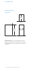
S I T E PR EPAR ATION Opening Dimensions I C E MACHINE 24" (610) OPENING DEPTH TOP VIEW 34 1/2" 15 1/4" (876) OPENING HEIGHT (387) OPENING WIDTH SIDE VIEW FRONT VIEW IMPORTANT NOTE: It is recommended that the electrical and water supply be placed in an adjacent cabinet. If they are placed within the opening, additional cabinet depth may be required. 4 | Sub-Zero Customer Care 800.222.
S I T E PR EPAR ATION Electrical Installation must comply with all applicable electrical codes. Although it can be located anywhere on the back wall, it is recommended that the electrical supply be placed in an adjacent cabinet or in the lower right of the opening. Refer to the illustration below. A separate circuit, servicing only this appliance is required. Model UC-15I(P)O is designed and safe for use in outdoor applications.
S I T E PR EPAR ATION Plumbing Preparation Installation must comply with all applicable plumbing codes. The water supply line should be located as shown in the illustration below. The water supply line should be connected to the house supply with an easily accessible shutoff valve. Do not use self‑piercing valves. A reverse osmosis system can be used provided there is constant water pressure of 20–80 psi (1.4–5.5 bar) supplied to the unit at all times.
I N S TALLAT IO N Installation 5 Open I N S TALL ICE MACHINE 1 Adjust the leveling legs close to the desired height. Refer to the illustration below. 2 Reverse the door swing if needed. Refer to steps outlined on page 9. 3 Gravity drain model: Install the drain hose provided, onto the drain fitting on the back of unit and route to the open site drain. Refer to the illustration below and plumbing requirements on the previous page.
I N S TALLAT IO N Installation V E R IF Y ICE PR ODUCTION 1 Press ‘POWER’ to turn the ice machine on. 2 Add one gallon (3.8 L) of cold water to the ice bin. Verify the water completely drains from the ice bin and there are no leaks. If the water has not drained within 60 seconds, there may be a kink in the drain tube or incorrect drain installation. 3 Press ‘CLEAN’.
I N S TALLAT IO N Installation 5 Remove R EVER S E DO O R SWING The door hinges are designed to be placed on either the right or left side of the ice machine. The unit is shipped with the door hinged on the right. Moving the hinges to the left in pre-drilled holes, allows for a left-hand door swing. To reverse door swing: the top cover of the ice machine by removing two screws at the top rear of the unit.
I N S TALLAT IO N Custom Panel O VER LAY PANEL PA N EL I N S TA LLATI O N For overlay applications, a custom door panel must be installed. Panel size is critical for a proper fit. To verify panel requirements and dimensions, refer to the Sub-Zero design guide at subzero.com/specs. Remove the handle side bracket attached to the front of the door. Place the custom overlay door panel face down on a protected work surface.
I N S TALLAT IO N Completion K I C KPLAT E INS TAL L ATION H I N GE C O V ER S Install the kickplate using two screws provided. Refer to the illustration below. The kickplate must be removable for service. The floor cannot interfere with removal. Do not cover the louvered section of the kickplate. Install hinge covers once installation of the ice machine is complete and door stop pins have been installed (if applicable). The knock-out in the hinge cover must be removed if the 90° door stop is used.
SUB- Z E RO, I NC. P. O. BOX 44848 MA D I SO N , WI 5 3 7 4 4 7024818 REV-C 8 / 2016 SU B ZER O . C O M 800.222.