
Installation Sheet

Undercounter Installation 8
Installation
IMPORTANT NOTE: I
f the undercounter unit has been laid
on its back or side, you must allow the unit to stand upright
for a minimum of 24 hours before connecting power.
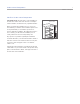
With the undercounter unit near the installation opening,
plug the power cord into the electrical outlet. With power
applied to the unit, check for lighting and cooling. Once
you are satisfied that the unit is operating properly, shut
off power to the electrical outlet at the circuit breaker and
proceed.
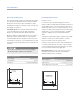
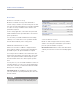
LEVEL THE UNIT
Level the unit before sliding it into position. Leveling
cannot be completed with the unit pushed back in the
installation opening.
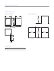
Using an adjustable wrench or pliers, turn each of the four
leveling legs clockwise to raise the unit and counterclock-
wise to lower the unit. For the location of the leveling legs,
refer to the illustration.
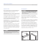
POSITION THE UNIT
Slide the undercounter unit back into position in the
installation opening. Make sure it contacts the anti-tip
bracket for a stable installation.
The undercounter unit provides the best access to its
contents when the front surface of the door panel extends
out from surrounding cabinets approximately
1
/4" (6).
WATER LINE CONNECTION (MODEL UC-24CI)
For model UC-24CI, connect the plastic tubing from the
ice maker to the house water supply line with the fitting
connection kit, provided. Check all water line fittings for
leaks.
Purge the water line prior to final connection to the unit.
This will remove any debris that may be present in the
tubing from installing the new water line.
IMPORTANT NOTE: Let your customer know that the ice
maker will not produce ice immediately, and that the first
few batches of ice produced should be discarded. Allow
24 hours for proper ice production.
IMPORTANT NOTE: Water lines must not be exposed to
freezing temperatures. Exposure could cause damage to
the unit and home.
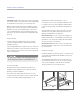
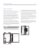
INSTALL KICKPLATE
Install the kickplate using the two #10 x
1
/2" stainless steel
screws that are provided with the kickplate. Refer to the
illustration below.
The kickplate must be removed for servicing. The floor
cannot interfere with removal. Do not cover the louvered
section of the kickplate to allow proper air circulation.
Turn power back on to the electrical outlet.
To reduce the possibility of the unit tipping forward, the
front leveling legs must be in contact with the floor.
LEVELING LEGS
Location of leveling legs. Kickplate installation.
KICKPLATE