
Installation Instructions


subzero.com
|
5
Electrical
Installation must comply with all applicable electrical codes.
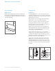
The electrical supply should be located within the shaded
area shown in the illustration below. A separate circuit,
servicing only this appliance is required. A ground fault cir-
cuit interrupter (GFCI) is not recommended and may cause
interruption of operation.
IMPORTANT NOTE: The electrical outlet must be placed so
the grounding prong is to the right of the thinner blades.
The outlet must be ush with the back wall.
ELECTRICAL REQUIREMENTS
Electrical Supply 115 VAC, 60 Hz
Service 15 amp
Receptacle 3-prong grounding-type
WARNING
Do not use an extension cord, two-prong adapter or
remove the power cord ground prong.
Preparation
To operate properly, the door must open a minimum of 90°.
Use a minimum 3"
(76) ller in corner installations to assure
a 90° door opening.
Uncrate the unit and inspect for damage. Remove and
recycle packing materials. Do not discard the kickplate, anti-
tip bracket, hardware and the leveling legs which hold the
wood base to the bottom of the unit.
Anti-Tip Bracket
WARNING
To prevent the unit from tipping forward, the anti-tip
bracket must be installed.
MODEL UW-24
The anti-tip bracket should be attached to the wall behind
the unit with the bracket ange located
1
/4" (6) above the top
of the unit. Refer to the illustration below. Failure to properly
position the anti-tip bracket will prevent proper engagement.
For installations that cannot accommodate the anti-tip
bracket, a countertop bracket is provided to secure the unit
to the countertop. Refer to the illustration below.
MODEL UW-24 / UW-24FS SITE PREPARATION
3" (76)
15
1
/2"
(394)
2"
(51)
LEFT SIDE
OF OPENING
FLOOR
Electrical supply location.
1
/4" (6)
ANTI-TIP
BRACKET
COUNTERTOP
BRACKET
Anti-tip bracket (UW-24).
Countertop bracket.