CONTENTS Section Tifle Page 1. SPECIFICATIONS ....................................................................................................... 1 2. PERFORMANCE ........................................................................................................ 2 2-1 MAXIMUM OUTPUT ......................................................................................................... 2 2-2 MAXIMUM TORQUE ...........................................................................................
Section 8. CARBURETOR Title ........................................................................................................ 8-1 OPERATION AND FUNCTION....................................................................................... 8-2 COMPORNENT PARTS ................................................................................................. Page 47 47 49 .............................................................................................. 9.
1 SPECIFICATIONS MODEL Type EH65V EH63V Air-Cooled, 4-Cycle, V-Twin Cylinder, Vertical P.T.O. Shaft, OHV Gasoline Engine Bore x Stroke 2-80 mm x 65 mm (3.15 x 2.56 in.) Piston Displacement 653 cm3 (39.8 cu.in.) Compression Ratio 8.3 Maximum Output Max. Torque Direction of Rotation kW (18.0 HP) /3600 r.p.m. - 43.3 N.rn(4.41 kgf m) /2000r.p.m. 45.6 N.rn(4.
2. PERFORMANCE 2-1 MAXIMUM OUTPUT The maximum output is the output of a.n engine with its throttle valve fullyledopen under the cmdition that all the moving parts are properly broken in after the initial break-in period. A new engine maynot produce full maximum output while its moving parts are stillnot broken-in.
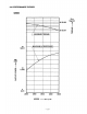
2-3 PERFORMANCE CURVES EH63V N-m 45 (4.59) 35 (3.57) MAXIMUM TORQUE .I 15 (20.11 t I - MAXIMUM HORSEPOWER I t I 10 (13.4) 5 (6.7) 2000 2400 SPEED 2800 3200 r.p.
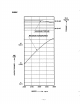
EH65V N-m X /1 W 35 (3.57) /MAXIMUM TORQUE I 3 0 K 0 F I MAXIMUM HORSEPOWER \ I I I 15 (20.1 /" 10 (13.4) 5 (6.7) 2000 2400 SPEED 2800 3200 r.p.
3. FEATURES The overhead valve arrangementis adopted for ensuring high power, low fuel consumption and low oil consumption. The adoption of twin-cylinder in theangle of90 degree (V arrangement) and crankcasein one piece, plastic blower housing etc. offers a compactness and light weight, making the arrangements for installin the engine much easier for various powered equipments.
4. GENERAL DESCRIPTIONOF ENGINE COMPONENTS /" ROBIN EH63V/ 65V series engineis air-cooled, 4-stroke, twin-cylinder,OHV arrangement gasoline engine. The twin-cylinderis located in the angleof 90 degree;#I cylinder is in the RH side and#2 cylinder in LH side as viewed from flywheel (cooling fan) side. 4-1 CYLINDER AND CRANKCASE The twin-cylinderand crankcase is single piece aluminum die-casting. The cylinder liner, made of special cast iron, is molded into the aluminum casting.
4-4 CONNECTING ROD AND PISTON The connectingrod is forged aluminum alloy, and its large and small ends function as bearings. The piston is an aluminum alloy casting, and carries two compression rings and one oil ring. Fig. 4-4 4-5 PISTON RINGS The piston rings are made of special cast iron. The profileof the top ringis barrel face and the second ring has a tapered face. The oil ringis designed for better sealing and less oil consumption, in combination with3 pieces.
4-7 CYLINDER HEAD The cylinder head is an aluminum die-casting which utilizes semi-spherical type combustion chamber for the high combustion efficiency. f' Fig. 4-7 4-8 VALVE ARRANGEMENT The intake valveis located on flywheel side of the cylinder head. The cooling finsand passages design lead cooling airto the exhaust valve area for the optimum cooling. Hard alloy valve seats are moldedin the cylinder head and stellite is fused to the exhaust valve face. ,A INTAKE VALVE EXHAUST VALVE Fig.
4-10 COOLING SYSTEM The large fins on the flywheel provide sufficient cooling air capacity for cylinder and cylinder head. The cylinder baffle helps the cooling air flow efficiently. 4-11 LUBRICATION SYSTEM The engineis furnished with full pressure lubrication system. The trochoid type oil pump is driven by crankshaft and delivers pressurized engine oil through the full-flow type oil filter to the journal and pin portions of crankshaft and camshaft.
4-14 CARBURETOR The engineis equipped witha horizontal draftcarburetor thathas a float controlled fuel system and a fixed main jet. The carburetors are calibrated carefully for sure starting, good acceleration,less fuel consumption and sufficient output.
4-17 SECTIONAL VIEW OF ENGINE \ CAMSHAFT / oti PUMP CRANKSHAFT Fig.
OIL PRESSURE SWITCH PUMP FUEL CRANKSHAFT PISTON RING CARBURETOR ROCKER COVER EXHAUST HEAD ELECTRIC STARTER SPARK PLUG CYLINDER Fig.
5. DISASSEMBLY AND REASSEMBLY 5-1 PREPARATIONS AND SUGGESTIONS When disassemblingthe engine, memorize the locationsof individual parts so that they can be reassembled correctly. If you are uncertain of identifying some parts,it is suggested that tags be attached to them. Have boxes ready to keep disassembled parts by group. To prevent losing and misplacing, temporarily assemble each group of disassembled parts. Carefully handle disassembled parts, and clean them with washing oil if necessary.
5-3 DISASSEMBLY PROCEDURES w Parts to remove Step Engine oil drain 1 Remarks and procedures Drain engine oil by removing plugs located on both sides of crankcase. OIL DRAIN Fig. 5-2 - 14- Fasteners , " .
Step 2 3 Parts to remove Fasteners Remarks and procedures Air cleaner cover and elements Air cleaner base Remove breather pipe from #1 cylinder head. CLEANER BASE /- GASKET, cleaner / ” ” “ CLEANER COVER BREATHER PIPE Fig. 5-3 Fig. 5-4 15 - M6 nut ; 2 pcs.
I Parts remove to 1 I 4 5 I I I I I I Fuel pump bracket I Remarks and procedures Fasteners I M6x14 ; 1 pce. M6x28 ; 1 pce. Remove pulse pipe and fuel pipe. Rotating screen and Blower housing M4x20 ; 4 pcs. M6x14 ; 6 pcs. M4 SCREW AND WASHER :4 pcs. - / 4 RT PULSE PIPE U I FUEL FILTER ’”I Fig.
Step Parts to remove Fasteners Remarks and procedures Take out carburetor alongwith governor rod, rod spring and choke control rod. Carburetor 6 Governor lever and speed control bracket INSULATOR M5 BOLT AND WASHER :1 pce. @ \ LEVER CHOKE ! SPACER FLANGE BOLT : 1 pce. CHOKE CONTROL ROD BRACKET, speed control M6 NUT : 1 pce. / -.J \ M5 NUT :1 pce. M5 BOLT AND WASHER : 1 pce. GOVERNOR LE RETURN SPRlN I \ ROD SPRING I SPEED CONTROL LEVER M6 FLANGE NUT : 1 pce.
Step 1 Parts to remove I Remarks and procedures I Fasteners I /? Ignition cojl 8 9 1. Take out plugcap. 2. Remove ignition coil. 3. Cut out stopwire fixing bands. 4. Disconnect stop wires from ignition coil. I 10 I Intake manifold I M6x30 bolt & washer ; 4 pcs. I I Remove flywheel from crankshaft by using puller. Flywheel M6 BOLT AND WASHER : 4 pcs. M8 flange nut ; 4pcs. M I 8 nut, washer, spring washer SPRING WASHER M6 BOLT AND BLOWER UNIT Fig- 5 8 M6 BOLT AND WASHER : 2 pcs.
11 I I I I Step Parts to remove Remarks and procedures Fasteners M6x18 ; 2 pcs. Regulator - M6x12 ; 6 pcs. Cylinder baffles (#1, #2,#3,#4) to IGNITION COIL toCOIL IGNITION FLANGE BOLT :4 pcs. CYLINDER BAFFLE 5 FLANGE BOLT :2 pcs.
Step Parts to remove Remarks andprocedures Fasteners 13 Electric starter M8x65 ; 2 pcs. 14 Charge coil M5x20;4pcs. 15 Spark plug NGK : BPGES or BPRGES I Fig.
I remove Parts to I Remarks procedures and M6x12 ; 4 pcs. Rocker cover 16 Temporally fit theflywheel,when removing rocker arm,turn and adjust flywheel at TDC with the marking" T faced to "1 or "2" on each cylinder head. Cylinder head, Push rod, Rocker arm andoil filler 17 Fasteners MlOx65 ; 8 pcs. I' PIVOT BOLT pivot : 2 pcs. M6 NUT :2 pcs. GUIDE PLATE SUPPORT, blower housing I 'I A" LIFTING EYE 1 I ! M10 FLANGE M6 FLANGE BOLT :2 pcs. \ I LIFTING EYE 2 I, BOLT:4pcs.
Step Parts to remove Remarks and procedures Fasteners /? 18 Intake & exhaust valves Breather cover Breather plate EXHAUST VALVE Fig.
Parts to remove Main bearing cover *Oil pump 'Oil filter *Oil pressure switch *Oil relief spring & ball I Remarks procedures and Take out key from PTO shaft. Wrap PTO shaft with polyvinyl tape not to damage oil seal by key groove edge. I Fasteners M8x44 ; 7 pcs. M8x75 ; 3 pcs. Fig. 5- 16 GOVERNOR GEAR SHAFT M8 FLANGE MAIN BEARING SHAFT, oil pump OUTER ROTOR OIL PUMP COVER f i g .
Step Parts to remove Remarks and procedures Fasteners r? Mate the markings both on Camshaft and tappet 20 crankshaft gear andcamshaft gear and then takeout camshaft. Fig. 5-18 h i . '. \ - p""""' 9 TAPPET Fig.
~~ ~ ~ Parts to remove Step Piston and Connecting rod 'Piston pin clips 'Piston pin 'Piston rings ~ ~~ Fasteners Remarks and procedures 1. Remove connecting rod bolts. 2. Take out connecting rod cap. 3. Push the connecting rod upwards and take out along with piston. M8 ; 4 pcs. 21 22 Crankshaft CUP \ PISTON CONNECTING PIN - Put the markingof original position onto each piston, ring, clip, piston pin, connecting rod and cap for reassembly. 1. Remove key from crankshaft. 2.
Step 23 Parts to remove Remarks and procedures Fasteners Crankcase *Governor levershaft *Leaf valve CRANKCASE 7 GOVERNOR LEVER LEAF VALVE / RETAINER PLATE M4 SCREW AND WASHER : 2 pcs I/" SNAP PIN Fig.
5-4 REASSEMBLY PROCEDURES 5-4-1 PRECAUTIONS FOR REASSEMBLY 1) Clean parts thoroughly before reassembly. Pay most attentionto cleanliness of piston, cylinder, crankshaft, connecting rod and bearings. 2) Scrape off all carbon deposits from cylinder head, piston top and piston ring grooves. 3) Check lip of oil seals. Replaceoil seal if the lip is damaged. Apply oil to the lip before reassembly. 4) Replace all the gaskets with new ones. 5) Replace keys, pins, bolts, nuts, etc., if necessary.
B. CYLINDER HEAD. VALVES and ROCKER ARM ~ NOTE ; Clean valves and wash cylinder head thoroughly. Remove carbon and gumdeposits from thevalves, seats, ports and guides. Inspect valves, valve seats and varve guides. * Replace valves thatare badly burned, pitted orwarped. Valve guides should be replaced when valve stem cIearance exceeds specifications. (Refer to SERVICE DATA for clearance specifications. ) If exceeds, draw valve guides out and press new guides in.
C. PISTON and CONNECTING ROD m (1) Install oil ring first, then second ring and top ring. Spread ring only far enoughto slip over pistonand into correct groove.Use care not to distort ring. NOTE ; * Install second ring with punched mark beside the gap face upward. * Top ring canbe fit either way. * As for oil ring, rails should be placed on and below the expander. (2) Apply enough oilto small end of connecting rod and piston pin, and fix connecting rod to piston with piston pin.
D.Main bearina cover and aovemor aear (1) Insert washerinto governor gear shaft. (2) Insert governor gear along with sleeve into governor gear shaft. (3) Insert ball and spring into the oil relief valve hole and tighten boltby the specified torque. - - - - Tightening Torque :6.9 8.8 N - m (70 90 kg acm, 5.1 6.5 ft Ib.) (4) Tighten oil drain plugs on both side of main bearingcover. GOVERNOR SLEEVE 7 GOVERNOR GEAR q-.
2) PISTON andCONNECTING ROD PISTON RING COMPRESSOR \A CONNECTINGROD (1) Install piston and connecting rod assembly into cylinder by using a piston ring compressor to hold piston rings. Note: The "1'I mark of the connecting rod for #I cylinder and "2" mark for #2 cylinder should be faced to the main bearing cover side when assembled. Apply enough oil to piston rings,connecting rod bearings (large end) and cylinder bore beforeassembly. * Set gaps of piston rings as shown in the illustration.
4) Adjust crankshaftend play (1) Adjust end playto the specified values using the proper spacer. The proper spacer may be determined following manner. i ) Measure the depth "A" (From the matingsurface to the boss.) ii) Measure the height "B" (From the mating surface to the crankgear.) - - - - - (B= 0- 0) (A+0.36)-B= SIDE CLEARANCE (mrn) (SIDE CLEARANCE)-0.2 mm =THICKNESS OF CRANKSHAFT SHIM (rnm) (A+O.O14)-B= SIDE CLEARANCE (in.) (SIDE CLEARANCE)-0.008 in.= THICKNESS OF CRANKSHAR SHIM (in.
5) MAIN BEARING COVER (1) Put a oilseal guide onto PTO shaft portion to avoid damaging the main bearing cover oil seal. (2) Place gasket ontothe mating surface of crankcase. (3) Lubricate oil seal lip potion and bearing surfaces, and install main bearing cover. Tighten bolts evenly to the specified torque. I - - - Tightening Torque:d 6.7 18.6 N-m (170 190 kg-cm, 12.3 13.7 ft-lb.
7) CYLINDER HEAD n NOTE ; Be sureto check dowel pin, and replacewith new one if damaged. A (1) Place new head gasket onto crankcase. (2) Install #I and #2 cylinder heads. Tighten bolts evenly in three steps by the specified torque. Tightening torque 1 st step 2 nd step 9.8 N .rn (100kg mcrn) (7.2ft Ib.) (200kg crn) - I Final Step 33.3-41.2N m (340-420kg 'crn) (24.6-30.4 ft Ib.) 19.6 N -rn - . (14.5 ft Ib.) 8 ) ROCKER ARMS AND PUSH RODS (I) Insert push rods into crankcase.
9) VALVE CLEARANCE ADJUSTMENT in position for easy operation. NOTE : Temporally fit the flywheel (1) Rotate crankshaft clockwiseto the TDC (top dead center)of compression stroke by matching the mark "T" of flywheel with the mark "1" of #1 cylinder head. (2) Loosen the nut on rocker am and turn the pivot to adjust the clearance between rocker arm and valve stem end, and then tighten the nut by the specified torque. - Valve Clearance:0.085 0.115 m m (Cold condition) (0.0033 0.0045 in.
10) ROCKER COVER Install rocker coverwith new gasket. - lightening Torque :6.9 8.8 N - m (70 90 kg cm) (5.1 6.5 ft . Ib.) - 11) BREATHER PIPE and COVER Attach breather plate (breather valve) and breather cover to crankcaseusing proper gaskets. & GASKET , breather plate I Put breather plate in such position as its reed valve opens outside. - (30 50 kg - cm) Note: GASKET, breather piate Never tightenthe bolts over the specified torque, or gasket is damaged and cut.
13) CHARGE COIL Install charge coil with the wiring located at 5o’clock position. - - lightening Torque : 1.5 3.4 N m (15 35 kg - cm) (1.1 2.5 ft .Ib.) - - 14) ELECTRIC STARTER Install electric starter. - Tightening Torque : 16.7 18.6 N * m (170 190 kg - cm) (12.3 13.7 ft - Ib.) - CHARGE CPlL ELECTRIC STARTER M8 FLANGE BOLT :2 pcs. Fig.
15)OIL FILLER and SUPPORT (BLOWER HOUSING) Install oil filler andsupport (blower housing) A 16) CYLINDER BAFFLE Attach cylinder baffle# I , #2, #3 and #4. 17)REGULATOR Attach regulatorto cylinder baffle. M6 FLANGE BOLT :4 pcs. 7 7 CYLINDER BAFFLE 5 Fig. 5-39 M6 FLANGE BOLT : 2 pcs.
18) FLYWHEEL (1) Wipe off oil and grease thoroughly from tapered portion of crankshaft and flywheel center hole. (2) Install flywheel to crankshaft and tighten flywheel nutwith spring washer and washer. - Tightening Torque :83.3 93.1 N - m (850 - 950 kg - cm) - (61.5 68.7 ft * Ib.) 19) INTAKE MANIFOLD Set gasket (special paper) onto both #I and #2 cylinder head and install intake manifold. - Tightening Torque :16.7 18.6 N * m (170 I90 kg cm) (12.3 13.7 ft .Ib.
22) GOVERNOR LEVER Attach governor rod and rod spring between governor lever and carburetor throttle lever,and insert the governor leverto governor shaft. Tighten locking bolt temporarily. 23) SPEED CONTROL LEVER and CHOKE LEVER Attach governor spring between governor lever and speed control lever as shown in the illustration. Attach chock control rod between carburetor chock lever and chock control lever. i I CHOKE I Fig. 5-41 M5 BOLT AND CONTROL ROD SPRING M6 FLANGE LEVER NUT :1 pce.
24) ADJUST GOVERNOR SYSTEM (1) Turn the speed control lever all the way toward the high speed position andit by fix tightening nut. (2) Check that governor leveris pulled by governor spring and carburetor throttle valve is fully open. (3)Turn governor shaft counterclockwise all the way and tighten lock bolt to secure the lever on the shaft. (4) Loosen the nut to allow the speed controllever to move freely. I U Fig. 5-43 25) BLOWER HOUSING Attach blower housing to crankcase.
28) OIL PRESSURE SWITCH Install oil pressure switch onto main bearing cover. Tightening Torque :5.9 - 9.8 N - m (60 -'IO0 kg - cm) (4.3 7.2 ft * Ib.) - Fig. 5-46 Apply oil to O-ringand install oil filter by tightening about 314 turns after attaching main bearing cover surface. lightening Torque :About 12.3 N - m (About 125 kg * cm) (About 9.0 ft Ib.) - A @ 0 RING Fig. 5-47 30)FUEL PUMP PLUSE PIPE Connect fuel pipe between fuel pump and crankcase nipple.
32) ENGINE OIL OIL LEVEL Refill engineoil and start the engine. Engine oil filter. oil will be lubricated oil passages and Check the engine oil level and refill again to the upper levelof oil level gauge. GAUGE OIL FILLER LEVEL Note: * Total engine oil capacity is about 2.0 L. * Use "SE"(API classification) or higher grade engine oil. Fig.
6. MAGNETO 6-1 OPERATION AND FUNCTION The ignition system is a pointless flywheel magneto with automatic advancing characteristic. Being different from the breakerpoint type ignition system,this system is completely free from such troubles as starting-up failure dueto dirty, burnt or corroded point surface. The electronic automatic advancing ensures extremely easy starts and stable high performance at operating speedby advancing the ignition timing to the most suitable point.
(2) At lower engine revolution, when the flywheel reached the ignition point the low speed ignition timing control circuit operates to run the basecurrent 13 to turnthe signal transistor A "ON" allowing the current I1 to bypass as current 14. At this moment the power transistor turns "OFF" and the current h is abruptly shut resulting in the high voltage generated in the secondary coil which producessparks at thespark plug.
7. LUBRICATION SYSTEM 7-1 OPERATION AND FUNCTION Full lubrication systemis adopted, in combination with torchoid oil pump and cartridge type oil filter. * The trochoid type oil pump is driven by camshaft, and delivers pressurized engine oil to the journal and pin portionsof crankshaft, camshaft etc. *The engine oilin the oil panis fed through the oil pump filter into oil pump andthe engine oil pressure is adjusted by the relief valve after discharging from oil pump.
8. CARBURETOR 8-1 OPERATION AND FUNCTION w 1 I 1 cum U Fig.
8-1-1 FLOAT SYSTEM The float system is consists of a float and a float valve, and maintains a constant fuel level during engine operation. The fuel flows from the fuel tank into the float chamber through float valve. ~ When the fuel rises to a specific level, the float rises, and when its buoyancy and fuel pressure are balanced, the float valve closes to shut off the fuel, thereby keeping the fuel at the predetermined level.
- 8-2 COMPORNENT PARTS Q . 1. Carburetor Ass’y 2. Slow jet Ass’y 3. Main nozzle 4. Float 5. Float valve 6. Float pin 7. Float chamber gasket 8. Float chamber compl. 9. Passage cover gasketfilter 10. Passage cover 11. Screw 12. Throttle shaftAss’y 13. Choke shaftAss’y 14. Choke leverAss’y 8-2 15. Chokearmreturnspring 16. Choke lever ring 17. Choke collar 18. Throttle valve 19. Screw, valve set 20. valveChoke 21. Needle compl. 22.Expansion plug 23.
9. ELECTRIC STARTER I NOTE; For Electric starter operation, electric wiring should be connected among etectric starter, key switch and battery as shownin the diagram. Oil Warning Lamp (Option Parts) " " " " " """"" t;\ """I f , I "-0 , I I I ~ I , , , I , , , , O , , I , I , , , I c r----T i""12V-30AH _" 4 fig. 9-1 9-1 OPERATION AND FUNCTION - When key switchis turned ON,lower electric current (M -+) flows through coilof magnetic switch andthe coil isexcited.
9-2 COMPORNENT PARTS Fig. 9-3 15. Gear case metal cover 16. Dust cover kit 17. Shift lever kit 18. Magnetic switch Ass’y 19. Through bolt 20. Bolt 21. M terminal cover 1. Starting motorAss’y 2.Armature Ass’y 3. Thrust washer kit 4. Pinion stopper set 5. Yoke Ass’y 6. Rear coverAss’y 7. Starter metal 8. Brush holderAss’y 9.Brush (-) 10. Brush set 11. Brush spring 12. Pinion Ass’y 13. Gear case Ass’y 14.
IO. TROUBLESHOOTING The following three conditions must be fulfilled for satisfactory engine start. (1) The cylinder filled with a proper fuel-air mixture. (2) Good compressionin the cylinder. (3) Good spark, properly timed, to ignite the mixture. are met. The engine cannotbe started unless these three conditions There are also other factors which make engine start difficult, e.g., a heavy load on the engine whenit a high back pressure dueto a long exhaust pipe.
10-2 STARTING DIFFICULTIES Phenomenon Possible causes Remedy Charge battery 1) Battery discharged 2) Poor connection between battery and starter motor Clean or repair 1. Low engine speed at starting I faulty 4)starter Electric repiaceorRepair Replace with recommended engine oil - 5) Improper engine oil 2.
10-3. INSUFFICIENT OUTPUT Possible causes 2. Ignition system malfunction 3.
10-5. ROUGH IDLING Possible causes ~ I I 2. Intake svstem tem I 3.Cylinder head I Remedy I I 1) Low idling speed I Adjust I 2) Carburetor slow system passage clogged I Checkandclean 1) Air mixing from connecting portionof air intake I 4.
10-7. HIGH FUEL CONSUMPTION Phenomenon 1. Fuel system I I ~ Possible causes Remedy I ~ 1) Over-size mainjet 2) Needle valve faulty and/or high fuel level in float chamber Replace Adjust or replace I 3) Chock valve does not open fully. Repair or replace 2. Engine core 1) Low compression Check or repair Check and adjust load and/or engine speed 10-8. DETONATION I Phenomenon 1. Ignition system malfunction 2. Fuel system malfunction 3.
10-9. ENGINE MISFIRE Possible causes Phenomenon 1.
11. INSTALLATION Engine life, ease of maintenance and inspection, frequency of checks and repairs,and operating cost a l l depend on the engine. the way in which the engine is installed. Reviewthe following instructions carefully for installing 11-1 INSTALLING When mounting the engine, carefully examine its position, the method of connecting it to a machine, the foundation, and the methodof supporting the engine.
12. SERVICE DATA 12-1 CLEARANCE DATA AND LIMITS Unit : mm (in: EH63V / 65V ITEM STD Limit 0.05or less (0.002or less) (0.004) 0.7- 1.0 (0.028- 0.039) 2.0 (0.079) 6.035- 6.053 (0.2376- 0.2383) 6.15 (0.242) CYLINDER HEAD Flatness 0.1 Valve seat contact width IN. EX. Valve guide inside dia.
Unit :mm (in) ~ EH63V / 65V ITEM ~~ ~ STD I Limit CYLINDER inside dia. * STD 80.000- 80.019 (3.1496- 3.1504) To be rebored when :he difference between nax. and min. of liameter reachedto 1.1 (0.004). 1 st reboring 80.250- 80.269 (3.159- 3.160) Ditto 2 st reboring 80.500- 80.519 (3.169- 3.170) Roundiness after reboring. 0.01 (0.004) * Cylindricity after reboring. 0.015 (0.0006) PISTON * Piston size (At skirtin thrust direction) STD t 1 sto/s 2nd o / s 79.968- 79.988 (3.148- 3.
Unit :mm (in) EH63V / 65V ITEM STD 'ISTON Ring groove side clearance Limit 0.05 - 0.09 (0.0002- 0.0035) 0.1 5 (0.006) 2nd 0.03 - 0.07 (0.0012 - 0.0028) 0.15 (0.006) Oil ring 0.057-0.175 (0.0022- 0.0069) 0.15 (0.006) 20.989 - 21.002 (0.8263- 0.8269) (0.8281) 20.991 - 21 .OOO (0.8264- 0.8268) 20.960 (0.8251) 0.012 - 0.051 (0.0005- 0.0020) 0.25 (0.0098) 0.2 - 0.4 (0.0079- 0.01 57) (0.0591) 0.2 - 0.7 (0.0079- 0.0276) 1.5 (0.0591) ' Piston pin hole 21.035 ' Piston pin outside dia.
Unit : rnm (in) EH63V 165V STD Limit 39.000 - 39.016 (1-5354- 1.5361) 39.100 (1.5394) 0.030 - 0.060 (0.0012 - 0.0024) 0.2 (0.0079) 21.010 - 21.023 (0.8272 - 0.8277) 21.080 (0.8299) 0.010 - 0.032 (0.0004 - 0.0013) 0.12 (0.0047) CONNECTING ROD * Big end inside dia. 120' Clearance between big end and crankpin * * Small end inside dia. Clearance between small end and piston pin * Big end side clearance - 0.1 0.4 (0.0039 - 0.0157) 1.0 (0.0394) 30.956 - 30.970 (1.5337 - 1-5343) 38.90 (1.
Unit :m m (in) E ITEM STD Limit 36.1 - 36.3 (1.4213- 1.4291) 35.95 (1.4154) 19.967 - 19.980 (0.786l - 0.7866) 19.950 (0.7854) IN. 5.970 - 5.985 (0.2350- 0.2356) 5.85 (0.2303) Ex. 5.960 - 5.975 (0.2346- 02352) a :AMSHAFT Cam height (IN. and EX.) EH63V / 65V ’ Journal outside dia. “D”type JALVE ’ Valve stem outside dia. ‘Clearance between vatve stem dia. and valve guide. 5.85 (0.2303) IN. 0.050 - 0.083 (0.0022- 0.0033) 0.30 (0.0118) w. 0.060 - 0.093 (0.0024- 0.0037) 0.30 (0.
Unit : mm (il EH63V/65V ITEM ~ STD Limit 8.960- 8.975 (0.3528- 0.3533) 8.93 (0.3516 ) 9.00- 9.015 (0.3543- 0.3549) 9.08 (0.3575) 0.025 - 0.055 (0.0010 - 0.0022) 0.15 (0.0059) FAPPET Stem outside dia. I I Guide inside dia Tappet guide clearance dALVE SPRING FREE LENGTH 39.5 (1.5551) ~~~~ ~~ ~~~ ~~~ ~ ~ VALVE SEAT ANGLE (IN. and EX.) ' Valve cutter angle (a) ' Valve contact width(b) H a : 90" b 0.7- 1 .O (0.028- 0.039) - 64- 2.0 (0.
12-2 TORQUE SPECIFICATIONS Tightening Torque ITEMS N-m Kg-cm ft-lb. Breather cover 2.9 - 4.9 30 - 50 2.2 - 3.6 Carburetor b o k 6.9 - 8.8 70 - 90 5.1 - 6.5 Charge c o i l 1.5 - 3.4 15-35 22.1 - 27.0 225 - 275 - 2.5 16.3- 19.9 - 41.2 340 - 420 83.3 - 93.1 850 - 950 61-5 - 68.7 6.9 - 8.8 70 - 90 5.1 - 6.5 Connecting rod cap bolts Cylinder head b o k Flywheel nut Ignition c o i l - Intake manifold bolts 16.7 18.6 Main bearing cover bolts 1 Oil filter I 12.3 33.
12-3 OIL GRADE CHART Use oil classified asSE or higher. Multi-grade oil tends to increase its consumptionat high ambient temperature.
e 13. MAINTENANCE AND STORAGE 13-1 DAILY MAINTENANCE Every day before operating engine, check the following items; _ _ ~~ ~ ~~ ~ ~ REMARKS MAINTENANCE ITEMS Governor linkage is especially sensitive to dust. 1) Clean away dust and chaff from engine. r 2) Check fuel leakage from fuel system. If any, retighten fasteners or replace necessary parts. ~ ~~ ~ Loose bolts and nuts may come off and result in 3) Inspect for loose hardware and retighten if breakage of other parts. necessary.
Every Maintenance Items Clean engine and check bolts and nuts 8 hours (daily) X (Daily) I Every Eve@ Every 50 200 500 Every 1,000 hours hours hours hours I X (Refill Check andrefill engine oil l daily to full level.
13-3ENGINE STORAGE (1) Change the engine oil a n d perform the daily maintenance items above mentioned. (2)Drain fuel from carburetor float chamber. (3)To prevent rust in the cylinder bore, applyoil through t h e spark plug hole and turn the crankshaft several turns by hand. Reinstall the plug. (4) Turn the crankshaftby hand andleave it where the resistanceis the heaviest. (5)Clean outside of the engine with oiled cloth.
SU6ARU ~bin America, 940 LivelyBlvd. l Wood Dale, IL 60191 e-mail: sale.s@robinamerica.com l l Inc. Phone:630-350~8200 l Fax:630-350-8212 www.robinamerica.