ROBIN AMERICA, INC.
CONTENTS Section Title . Page 1 SPECIFICATIONS ............................................ 1 2. PERFORMANCE ............................................ 2 2.1 . 2.2 . 2.3 . Maximumoutput . . . . . . . . . . . . . . . . . . . . . . . . . . . . . . . . . . . . . . . Continuous Rated Output . . . . . . . . . . . . . . . . . . . . . . . . . . . . . . . . . Maximum Torque and Fuel Consumption Ratio a t Max Output . . . . . . . . . 3. FEATURES ............................................... 4 .
7 . MAGNETO 7.1 . 7.2 . 7.3 . 7.4 . ............................................... 18 Magneto . . . . . . . . . . . . . . . . . . . . . . . . . . . . . . . . . . . . . . . . . . . . . Breaker PointAdjustment . . . . . . . . . . . . . . . . . . . . . . . . . . . . . . . . . Timing Adjustment ..................................... Magneto Service Instructions . . . . . . . . . . . . . . . . . . . . . . . . . . . . . . . 18 18 18 8. GOVERNOR ADJUSTMENT 9.CARBURETOR ................................... ..
1.
2. PERFORMANCE 2-1MAXIMUMOUTPUT The maximum output of an engine is such standard power as developed by that engine, after its initial run-in period witha1 the moving parts properly worn-in, when operating with the fully open throttle valve. Therefore, it follows that enginemaynotdevelopthismaximumoutputinthebeginning,becausemovingpartsarenot in aproperly a nev w0rn-h condition.
3. FEATURES 1. A compact, lightweight, and highly durable 4cycle aircooled EYseries with high output, embodying ingenious design and advanced machining techniques. 2. 3. Simple construction, good appearance, plus easy start-up. Smooth speed control functions of governorguaranteesstableoperationundervariousloadconditionsoverawide range of applications. 4. Economical advantage with minimized fuel consumption. 5.
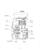
/- FLYWHEEL(COOLI~GFAN) I \ LIGHTING COIL CRANKCASE -4 -
SEl -5-
4-2 CRANKCASE The crankcase is made of aluminum die-cast and separable on driving shaft side with main bearing cover assembled. Provided on blower side are two ball bearings, each supporting the crankshaft and camshaft. 4-3 MAINBEARING COVER The aluminum die-cast main bearing cover on the driving shaft side allows easy access to the engine interior for inspection simply by removing it. The’fange and boss permit direct coupling of operating machines such as generators, pumps, etc.
4-10 GOVERNOR The centrifugal flyweight type governor assures constant-speed operation at selected speed, irrespective of load fluctuations. 4-11 COOLING The cooling fan which also serves as a flywheel forcily feeds cooling air to the cylinder head with the aid of cylinder baffles and head cover. 4-12 LUBRICATION Therotatingand slidingpartsarelubricatedbyscoopingandsplashingoilincrankcasewith oil scraperattachedto connecting rod.
5. INSTALLATION Since the installation method affects the service life, ease of maintenance, frequency of check and reapir, and operating costs of engine, the following contents should be carefully examined before installing your engine. For details, referto the separate “SALES MANUAL”-Engineering Information-. 5-1 MOUNTING When installing the engine, its mounting position, coupling conditions with operating machines, and anchoringor supporting methods must be carefully examined.
5-6 WIRING a JIS CB104 female terminal -e JIS CA104 male terminal -@ - JIS LA 104 or LA108 plate terminal The dotted parts are not supplied with the engine. " " " 5-6-1 ROPE STARTINGENGINE MAGNETO _"" . '-N / BUZZER (6"- 8 W ) SPARKPLUG Fig. 5-6-1 LAMP (12V.
6. DISASSEMBLY and REASSEMBLY 6-1 PREPARATIONS and SUGGESTIONS 1 ) When disassembling engine, carefully note mounting positions and methods of respective parts in order to be able to reassemble them correctly. Tag parts, if there is a possibility of confusion. 2 ) Prepare several boxes to keep parts belonging to respective groups together. 3 ) In order to prevent missing or misplacing, group related parts together, tentatively assembling them immediately after disassembling each sub-assembly.
I 209 99010 07 (Y790-350) 001 65085 00 Flywheel Puller Bolt I 1 Valve Spring Compressor 209 9901 1 07 (Y790-282) Valve Seat Cutter (45”) 209 9901 2 07 1 (H640-118) 1 Pilot Stem 6-3 DISASSEMBLY and REASSEMBLYPROCEDURES 6-3-1 FUEL TANK and TANK BRACKET 1) Disconnect fuel pipe between fuel strainer and carburetor from carburetor. 2) Detach fuel tank from its mounting bracket (8mm nut X 4). 3 ) Detach bracket and head cover from cylinder head (8mm bolt X 2).
6-3-6 STARTING PULLEY and FLYWHEEL (magneto) Remove 3 piecesmountingboltstodetachstarting pulley from flywheel. Remove flywheel from crankshaft. nut,and 18mm or box wrench into an Insert a socket wrench give thewrenchasharpblowwithasoft hammer. Remove nut and spring washer. AttachflywheelpullertoflywheelasshowninFig. 6-3-1, andturncenterboltclockwiseuntilflywheel becomes loose enough to be removed. Disconnecthightensioncable of ignitioncoilfrom Fig.
In reassembly; 1) Clean carbon and gum deposits from the valves, seats, ports and valve stem holes. 2) Replace valves, if badly burned, pitted or warped. 3) Correct the valve seat by using 45" seat cutter tool as illustrated in 1.2-1 S m m (.04-.05 4) Fig. 6-3-3. The seat should be finished to inch) in width. Cylinderblockshouldbereplaced if valve stemclearancebecomesexcessive.'Referto Fig. ..-' 4 for clearance specifications and proper assembly.
6) ADJUSTING TAPPET CLEARANCE (Fig. 6-3-5) * Rotate crankshaft until tappet position,hold is in its lowest valve downandinsertfeelergauge between valve andtappetstem.Theclearancefor both intake and exhaust, with engine cold. 0.13-0.17mm * (0.0051”to 0.0067“) If clearance is less than specified, slightly grind valve stem and measure it again. * If clearance is largerthanspecified,sink valve seat to adjust clearance.
In reassembly; 1)Whenreassemblingmainbearingcover,assemblegovernorlevershaftandgovernorarmbeforereinstallingthem into crankcase. NOTE: If replacement of oil seal is required, force-fit new oil seal before reassembly. 2) When reassembling main bearing cover, apply oil to bearing surfaces, gear train, tappets, and oil seal lips, and form a thin film of oil o n main bearing cover face. Mount an oil seal guide onto .crankshaft to prevent damage t o oil seal lips.
In reassembly; PISTON RING (See Fig. 6-3-10) to prevent ring from 1) Use ring a expander tool becomingdistorted or brokenwhen installing onto piston. Ifanexpandertool is notavailable,installringsby placing the open end of the ring on first land of piston. Spread ring only far enough to slip over piston and into (Fig. correct groove, being careful not to district ring. 6-3-1 0) NOTE: With or without expander tool, assemble bottom ring firstand work upward, installing top ring last.
5 ) Check if connecting rod moves smoothly after reassembly. Clamping torque of connecting rod cap is 250-300 kg-cm ( 1 8-21.7 ft-lbs). D (crankshaft pin Dia.) W (crankshaft pin Width) PISTON TO CYLINDER AT PISTON SKIRT THRUST FACE (CLEALANCE) 0.15OL-0.189L (.0059”L-.0074”L) 0.155L-0.177L (.0061“L-.0070”L) TOP RING SECOND RING O I L RING 0.05L-0.25L (.0020”L-.0098“L) 0.05L-0.25L (.0020”L-.0098”L) SKIRT R I N G 0.2L-0.4L (.0079”L-.0157”L) 0.3L-0.5L (.0118”L-.
7 . MAGNETO 7-1 M A G N E T O In Models EY33-2 and EY44-2, ignition sparkis furnished by a magneto. The magneto is composed of the flywheel, ignition coil, lighting (charging) coil, breaker assembly (including condenser). The flywheel is mounted on crankshaft, while ignition coil, lighting coil, and breaker assembly are directly assembled to crankcase. 7-2 B R E A K E RP O I N TA D J U S T M E N T The breaker points are mounted inside flywheel and directly assembled to crankcase.
For timing adjustment, the following alighment marks areprovided: D type: D markatlowerleftcrankcase (see Fig. 7-3-1) M mark and slit on flywheel circumference B type: B mark atupperleftcrankcase M mark and slit on flywheel circumference. e- FLYWHEEL Fig. 7-3-I Fig. 7-3-2 For timing adjustment, the following procedures using a timing light: (See Fig- 7-32) Disconnect the stop button lead wires and the coil primary wire. Remove blower housing from engine.
*CHECKING IGNITION SPARK Remove spark plug from cylinder head and place it on cylinder head fin after connecting ignition cable to it. Crank engine several times by starting pulley, and check if plug gap spark is strong or weak. If spark is weak, check it according to steps 1 )-3) above. Correct plug gap is 0.6 to 0.7mm (.0236"".0276").
8. GOVERNOR ADJUSTMENT EY33-2 and EY44-2 employ a centrifugalflyweighttype governor which is mounted on a cam gear to automatically regulate throttie valve of carburetor by mean of a lever, so that the engine speed is kept constant irrespective of load fluctuations. Foradjustment,observefollowingprocedures. (seeFig. 8-1 ) 1)' Connectcarburetorthrottle lever andgovernor lever with connecting rod, and mount them onto governor shaft. 2 ) Connect governor lever and control lever with governor Fig.
9. CARBURETOR 9-1 OPERATION and CONSTRUCTION (see Figs. 9-1-1 and 9-1-2) 9-1-1 FLOAT SYSTEM The float chamber is located just below carburetor main body and serves to maintain the fuelI.eve1 at a consitant height by a joint action of float (F) and needle valve (NV) incorporated. The fuel flowsfrom the fuel tank into float chamber via needle valve, which is kept open while the fuel level is low, but closed when the fuel level reaches a predetermined level c o w i n g the float to move up.
9-1-2 PILOT SYSTEM This pilot system feeds fuel to engine during idle and low speed operation. The fuel fed through main jet (MI) is measured b y pilot jet (PJ), mixed with air measured by pilot air jet (PAJ), regulated by pilot screw, and then fedto engine through pilot outlet (PO) and bypass (BP). The fuel is mainly fed from pilot outlet(PO) during idling. 9-1-3 MAIN SYSTEM This system feeds fuel to engine during medium and high-speed operation.
9-2-3PILOT 1) SYSTEM Remove pilot jet (5) using a suitable tool while taking care not 2) Detach pilot screw t o damage it. (6) and spring (7). h In reassembly; 1) Clamp pilot jet securely, otherwise fuel leaks, causing engine failures. 2) If the tapered portion of pilot screw is deformed, replace it with new one. Avoid clamping it too tightly. 9-2-4 MAIN 1) SYSTEM Detach main jet holder (23), and remove float chamber body 2) Detach main jet (22) (20). from main jet holder ( 2 3 ) .
10. RUN-IN OPERATION OF ENGINE after REASSEMBLY An overhauled engine must be carefully run-in to get proper engine surface conditions on newly installed parts. A thorough run-in operation is indispensable particularly when cylinder, piston, piston rings,or valves are replaced. The recommended run-in schedule is as tabulated below. LOAD TIME SPEED EY33-2 EY44-2 I I I 10 minutes No load No load 2500 r.p.m. No load No load r.p.m. 10 minutes 3000 No load No load r.p.m. 10 minutes 3600 3.
1.1. TROUBLE SHOOTING For a satisfactory starting and running conditions of a gasoling engine, the following three requirementsmust be met: I. Thecylinder filled withaproperfuel-airmixture. 2. An appropriatecompressioninthecylinder. 3. Good spark at correct time to ignite the mixture. h If all three requirements are not met simultaneously, an engine can not be started.
11-1-3 ELECTRIC SYSTEM When there is no spark, the following must be checked. Disconnected cable leading to ignition coil, spark plug or contact breaker. Broken ignition coil winding, causing short circuit. 3) Wet or oil soaked spark plug cable. Dirty or wet spark plug. Incorrect spark plug electrode gap. Short connection of spark plug electrodes. Pitted or fused breaker points. Sticking breaker arm. Leaking or grounded condenser. Incorrect ignition timing.
8) Restrickedexhaust gas outlet. Carbon deposit in combustion space. 9) Engine detonating due to low octane gasoline with heavy load at low speed. 11-5 ENGINE KNOCKS 1) Gasoline of poor quality or low octane rating. 2) Engine operating under heavy load at low speed. 3) Carbon or lead deposits in cylinder head. 4) Incorrectsparktiming. 5) Losse or burntoutconnectingrodbearing. 6) Worn or loose piston pin. 7) Engineoverheated.
12. CHECKS and CORRECTIONS After dismantling and cleaning the engine parts, check them, and if necessary, correct them, according to the correction table. The correction table applies whenever the engines are repaired. Its contents should be thoroughly understood by those who undertake the repairing. Its specifications must be abided by to effect correct maintenance. Below, terms employed in the correction table are explained.
CORRECTION TABLE ENGINE MODEL STANDARD SIZE CORRECTION 1 TOLERANCE LIMIT I I Flatness of cylinder head EY33-2 EY44-2 EY33-2 78tJ Bore EY44-2 Roundness EY44-2 1 +0.057 -0.035 - 0.01 0.015 EY44-2 EY 33-2 EY44-2 Valve guide I.D. 8@ EY44-2 EY33-2 O.D. at skirt, in thrust direction (inch. over size) STD 0.251 0.50 77.87 ,~ 78.11 78.36 1 METHOD Correct " EY33-2 EY33-2 Surface plate, Feeler :ORRECTIOF 0.1 5 " Valve seat contact width I TOOL " I Cylindricity USE 0.15 0.
ITEM ENGINE MODEL STANDARD SIZE TOLERANCE TOOL 2ORRECTIOh METHOD 0 EY33-2 -0.008 Piston pin O.D. 0 EY44-2 Micrometer Replace Cylinder gauge Replace -0.009 E Y 33-2 +0.016 -0 Large end I.D. EY44-2 Clearance between rand large end I.D. and crankpin EY 33-2 0.080-0.1 1 2 E 44-2 Y 0.040-0.107 E Y 33-2 +0.038 +0.027 EY 44-2 +0.038 +0.025 Replace Small end I.D. Clearance between small end I.D. and piston pin Large end side clearance Parallelism between large end and EY 33-2 0.
r ENGINE MODEL ITEM I EY44-2 Journal O.D. 1 STAl:;RD Mag. TOLERANCE -0.003 S. 25@ 1 -0.01 2 I EY33-2 Free length EY44-2 , CORRECTION 46 USE LIMIT REMARKS TOOL :ORRECTIOF METHOD 0.05 0.05 Micrometer Replace -1.5 -1.5 Vernier calipers Replace Square Replace Micrometer Replace EU33--2 1.o Squarences EY44-2 For total length -0.030 -0.055 Valve stem O.D. -0.15 -0.1 10 Clearance between stem and guide EY33-2 Intake 0.030-0.09 1 EY44-2 Exhaust 0.090-0.146 0.
ITEM MODEL HP/rpm EY 33-2 8.013.600 REMARKS CORRECTION LIMIT Below 11 0% of rated output Max. Output EY44-2 lO.Ol3.600 EY33-2 613,600 EY 44-2 813,600 Continuous Rated output I ITEM I MODEL literlhr EY33-2 3.1 up 135% Standard Consumption Fuel Consumption EY 44-2 I REMARKS CORRECTION LIMIT I I I I I MODEL ITEM at Continuous Rated Output 3.
ITEM MODEL TOOL rpm REMARKS " EY33-2 Min. accelerating revolution Tachometer 1,150 EY44-2 ITEM MODEL kgcm ft-lb 450-500 32.5-36 TOOL REMARKS EY33-2 Cylinder head clamp nuts Torque wrench EY 44-2 EY33-2 Connecting rod bolts 250-300 18-2 1.7 Torque wrench EY44-2 EY 33-2 Magneto clamp nuts 800-1 O. OO 57.9-72.3 Toque wrench 170-190 12.3-13.7 Torque wrench 250-300 18-21.7 Torque wrench EY44-2 EY 33-2 Main bearing cover bolts EY 44-2 EY33-2 Spark plug EY44-2 -.
13. MAINTENANCE and STORING is operatedcorrectlyundernormalconditions.Theindicated Thefollowingmaintenancejobsapplywhentheengine no means guarantees for maintenance free operations during these intervals. maintenance intervals are by For example, if the engine is operated in extremely dusty conditions, the air cleaner should be cleaned every day, instead of every 50 hours.
13-5 EVERY 500 I - 600 HOURS (SEMIANUAL) CHECKS and MAINTENANCE 1 Checks and maintenance Reasons for requiring them The engine will be out of order. Remove cylinder head and remove carbon -\ deposit. Disassemble and clean carburetor. 13-6 EVERY 1000 HOURS (YEARLY) CHECKS and MAINTENANCE I 1 Checks maintenance and Perform overhauls, clean correct or replace Reasons for requiring them The engine output drops and become out ~~ ~~ -1 of order. parts.
Industrial Engines